
Toyota Corolla Cross: On-vehicle Inspection
ON-VEHICLE INSPECTION
CAUTION / NOTICE / HINT
CAUTION:
Do not remove the reserve tank cap and air release valve while the engine and radiator assembly are still hot. Pressurized, hot engine coolant and steam may be released and cause serious burns.
.png)
PROCEDURE
1. INSPECT RESERVE TANK CAP
CAUTION:
Do not remove the reserve tank cap and air release valve while the engine and radiator assembly are still hot. Pressurized, hot engine coolant and steam may be released and cause serious burns.
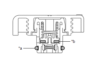
(a) Measure the valve opening pressure.
|
*a | O-ring |
|
*b | Rubber Packing |
(1) If there are water stains or foreign matter on the O-ring, clean it with water and finger scouring.
(2) Check that the O-ring is not deformed, cracked or swollen.
(3) Apply engine coolant to the O-ring and rubber packing before using a radiator cap tester.
(4) Install the radiator cap tester to the reserve tank cap.
| (5) When using the radiator cap tester, tilt it upwards 30° or more. |
|
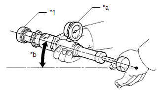
(6) Pump the radiator cap tester several times, and check the maximum pressure.
Pump Speed:
1 pump per second
|
Item | Specified Condition |
|---|---|
|
Standard pressure (for brand-new reserve tank cap) |
93 to 123 kPa (0.9 to 1.3 kgf/cm2, 13.5 to 18.0 psi) |
|
Minimum pressure (for used reserve tank cap) |
79 kPa (0.8 kgf/cm2, 11.5 psi) |
HINT:
Even if the reserve tank cap cannot maintain the maximum pressure, it is not a defect.
If the maximum pressure is less than the minimum pressure, replace the reserve tank cap.
(7) Remove the radiator cap tester from the reserve tank cap.


