Toyota Corolla Cross: Relay
On-vehicle Inspection
ON-VEHICLE INSPECTION
PROCEDURE
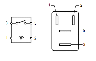
1. INSPECT FAN NO. 1 RELAY
| (a) Measure the resistance according to the value(s) in the table below.
Standard Resistance: |
Tester Connection | Condition |
Specified Condition | |
3 - 5 | Auxiliary battery voltage not applied between terminals 1 and 2 |
10 kΩ or higher | |
3 - 5 | Auxiliary battery voltage applied between terminals 1 and 2 |
Below 1 Ω | | |
(b) If the result is not as specified, replace the FAN NO. 1 relay.
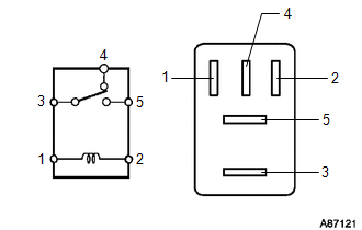
2. INSPECT FAN NO. 2 RELAY
| (a) Measure the resistance according to the value(s) in the table below.
Standard Resistance: |
Tester Connection | Condition |
Specified Condition | |
3 - 4 | Auxiliary battery voltage not applied between terminals 1 and 2 |
Below 1 Ω | |
3 - 4 | Auxiliary battery voltage applied between terminals 1 and 2 |
10 kΩ or higher | |
3 - 5 | Auxiliary battery voltage not applied between terminals 1 and 2 |
10 kΩ or higher | |
3 - 5 | Auxiliary battery voltage applied between terminals 1 and 2 |
Below 1 Ω | | |
(b) If the result is not as specified, replace the FAN NO. 2 relay.
3. INSPECT FAN NO. 3 RELAY
| (a) Measure the resistance according to the value(s) in the table below.
Standard Resistance: |
Tester Connection | Condition |
Specified Condition | |
3 - 5 | Auxiliary battery voltage not applied between terminals 1 and 2 |
10 kΩ or higher | |
3 - 5 | Auxiliary battery voltage applied between terminals 1 and 2 |
Below 1 Ω | | |
(b) If the result is not as specified, replace the FAN NO. 3 relay.
READ NEXT:
REMOVAL CAUTION / NOTICE / HINT COMPONENTS (REMOVAL)
Procedure Part Name Code
1 ENGINE WATER PUMP ASSEMBLY (WATER INLET HOUSING)
16032 -
- -
INSPECTION PROCEDURE 1. INSPECT WATER INLET WITH THERMOSTAT SUB-ASSEMBLY
CAUTION:
Do not put your hands into the water that has been heated for the inspection.
Touching the heated water
SEE MORE:
DESCRIPTION Refer to DTC P062712. Click here
DTC No. Detection Item
DTC Detection Condition Trouble Area
MIL Note
P12D41D Fuel Pump Control Circuit Current Out of Range
When the fuel pump control ECU operation duty ratio is 3 to 65%, overcurrent in the fuel
Inspection
INSPECTION
PROCEDURE
1. INSPECT FRONT SHOCK ABSORBER ASSEMBLY
(a) Compress and extend the front shock absorber assembly rod 4 times or more.
Standard:
When compressed and extended at a constant speed, the stroke of the shock absorber
rod is smooth with no abnormal resistance or