Toyota Corolla Cross Owners & Service Manuals

Toyota Corolla Cross: Removal

REMOVAL

CAUTION / NOTICE / HINT

COMPONENTS (REMOVAL)
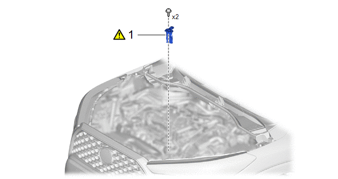
Procedure

Part Name Code

1

MASS AIR FLOW METER SUB-ASSEMBLY

22204

-

-

The necessary procedures (adjustment, calibration, initialization or registration) that must be performed after parts are removed and installed, or replaced during mass air flow meter sub-assembly removal/installation are shown below.

Necessary Procedures After Parts Removed/Installed/Replaced

Replaced Part or Performed Procedure

Necessary Procedure

Effect/Inoperative Function when Necessary Procedure not Performed

Link

Replacement of mass air flow meter sub-assembly

Inspection After Repair

  • Poor idle, etc.
  • Engine start function, etc.

PROCEDURE

1. REMOVE MASS AIR FLOW METER SUB-ASSEMBLY

(1) Disconnect the mass air flow meter sub-assembly connector.

(2) Remove the 2 screws and mass air flow meter sub-assembly from the air cleaner cap sub-assembly.
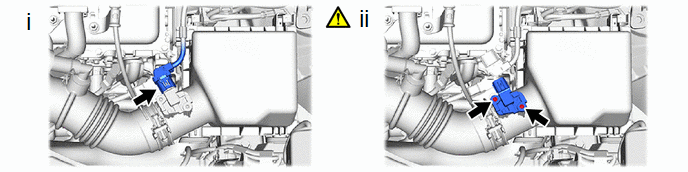
NOTICE:

If the mass air flow meter sub-assembly has been struck or dropped, replace it.

    READ NEXT:

     Inspection

    INSPECTION PROCEDURE 1. INSPECT MASS AIR FLOW METER SUB-ASSEMBLY (a) Perform a visual check for any foreign matter on the intake air temperature sensor (thermistor) of the mass air flow meter su

     Installation

    INSTALLATION CAUTION / NOTICE / HINT COMPONENTS (INSTALLATION) Procedure Part Name Code 1 MASS AIR FLOW METER SUB-ASSEMBLY 22204 - -

     Relay

    On-vehicle InspectionON-VEHICLE INSPECTION PROCEDURE 1. INSPECT NO. 1 ELECTRONIC FUEL INJECTION MAIN RELAY (EFI-MAIN NO. 1) (a) Measure the resistance according to the value(s) in the table be

    SEE MORE:

     Test Mode Procedure

    TEST MODE PROCEDURE REAR BRAKE PAD REPLACEMENT MODE *1 Rear Disc Brake Piston *2 Nut *a The nut moves inward in pad replacement mode HINT: When replacing the rear disc brake pad and rear disc, since the nu

     Drive Motor "B" Position Sensor Circuit "A" Circuit Open (P0C5513,P0C551F,P0C5F13,P0C5F1F)

    DTC SUMMARY MALFUNCTION DESCRIPTION These DTCs indicate that the resolver output signal is abnormal. The cause of this malfunction may be one of the following: Area Main Malfunction Description Inverter low-voltage circuit The connectors are not connected properly R

    © 2020-2026 Copyright www.tcorollacross.com PT NL