Toyota Corolla Cross Owners & Service Manuals

Toyota Corolla Cross: Removal

REMOVAL

CAUTION / NOTICE / HINT

COMPONENTS (REMOVAL)
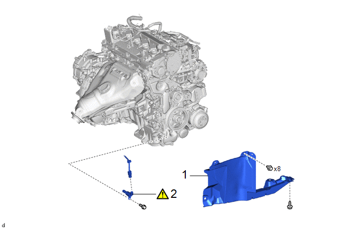
Procedure

Part Name Code

1

REAR ENGINE UNDER COVER RH

51443C

-

-

-

2

OIL PRESSURE CONTROL VALVE ASSEMBLY

15250

-

-

CAUTION / NOTICE / HINT

NOTICE:

This procedure includes the removal of small-head bolts. Refer to Small-Head Bolts of Basic Repair Hint to identify the small-head bolts.

Click here

PROCEDURE

1. REMOVE REAR ENGINE UNDER COVER RH

Click here

2. REMOVE OIL PRESSURE CONTROL VALVE ASSEMBLY

(1) Disconnect the oil pressure control valve assembly connector.

(2) Using an 8 mm socket wrench, remove the bolt and oil pressure control valve assembly from the No. 2 timing chain cover assembly.

    READ NEXT:

     Inspection

    INSPECTION PROCEDURE 1. INSPECT OIL PRESSURE CONTROL VALVE ASSEMBLY (a) Measure the resistance according to the value(s) in the table below. Standard Resistance: Tester Connection C

     Installation

    INSTALLATION CAUTION / NOTICE / HINT COMPONENTS (INSTALLATION) Procedure Part Name Code 1 OIL PRESSURE CONTROL VALVE ASSEMBLY 15250 - -

     Oil Pump

    SEE MORE:

     Inspection

    INSPECTION PROCEDURE 1. INSPECT SHIFT STROKE SENSOR (a) Connect 3 new dry-cell batteries (1.5 V each) in series. (b) Prepare a magnet or equivalent tool. (c) Connect a positive (+) lead from the batteries to terminal 2 (VDD) and a negative (-) lead to terminal 3 (GND). *a

     Generator Phase U Current Sensor Signal Bias Level Out of Range / Zero Adjustment Failure (P0E0028,P0E0428,P0E0828)

    DTC SUMMARY MALFUNCTION DESCRIPTION These DTCs indicate that the current sensor value is abnormal. The cause of this malfunction may be one of the following: Internal inverter malfunction Current sensor malfunction Inverter with converter assembly internal circuit malfunction DESCRI

    © 2020-2026 Copyright www.tcorollacross.com PT NL