Toyota Corolla Cross: Removal
REMOVAL
CAUTION / NOTICE / HINT
COMPONENTS (REMOVAL)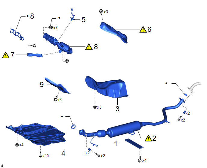
|
Procedure | Part Name Code |
.png) |
.png) |
 |
|---|---|---|---|---|---|
|
1 | FRONT FLOOR CENTER BRACE |
57533B | - |
- | - |
|
2 | FRONT EXHAUST PIPE ASSEMBLY (TWC: Rear Catalyst) |
17410 |
|
- | - |
|
3 | FRONT NO. 1 FLOOR HEAT INSULATOR |
58151 | - |
- | - |
|
4 | NO. 1 ENGINE UNDER COVER ASSEMBLY |
51410 | - |
- | - |
|
5 | AIR FUEL RATIO SENSOR |
89467B | - |
- | - |
|
6 | NO. 1 EXHAUST MANIFOLD HEAT INSULATOR |
17167 |
|
- | - |
|
7 | MANIFOLD STAY |
17118 |
|
- | - |
|
8 | EXHAUST MANIFOLD (TWC: Front Catalyst) |
17141 |
|
- | - |
|
9 | NO. 2 EXHAUST MANIFOLD HEAT INSULATOR |
17168 | - |
- | - |
|
● | Non-reusable part |
- | - |
CAUTION / NOTICE / HINT
The necessary procedures (adjustment, calibration, initialization or registration) that must be performed after parts are removed and installed, or replaced during exhaust manifold (TWC: Front Catalyst) removal/installation are shown below.
Necessary Procedures After Parts Removed/Installed/Replaced|
Replaced Part or Performed Procedure |
Necessary Procedure | Effect/Inoperative Function when Necessary Procedure not Performed |
Link |
|---|---|---|---|
| Inspection after repair |
|
|
CAUTION:
- To prevent burns, do not touch the engine, exhaust manifold or other high temperature components while the engine is hot.
.png)
- To prevent burns, do not touch the engine, exhaust pipe or other high temperature components while the engine is hot.
.png)
PROCEDURE
1. REMOVE FRONT FLOOR CENTER BRACE

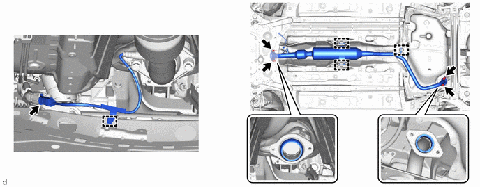
2. REMOVE FRONT EXHAUST PIPE ASSEMBLY (TWC: Rear Catalyst)
|
|
CAUTION:
|
3. REMOVE FRONT NO. 1 FLOOR HEAT INSULATOR
Click here
.gif)
4. REMOVE NO. 1 ENGINE UNDER COVER ASSEMBLY
Click here
5. REMOVE AIR FUEL RATIO SENSOR
Click here
6. REMOVE NO. 1 EXHAUST MANIFOLD HEAT INSULATOR
|
|
CAUTION: To prevent burns, do not touch the engine, exhaust manifold (TWC: Front Catalyst) or other high temperature components while the engine is hot. |

7. REMOVE MANIFOLD STAY
|
|
CAUTION: To prevent burns, do not touch the engine, exhaust manifold (TWC: Front Catalyst) or other high temperature components while the engine is hot. |

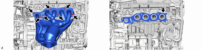
8. REMOVE EXHAUST MANIFOLD (TWC: Front Catalyst)
|
|
CAUTION: To prevent burns, do not touch the engine, exhaust manifold (TWC: Front Catalyst) or other high temperature components while the engine is hot. |
9. REMOVE NO. 2 EXHAUST MANIFOLD HEAT INSULATOR