Toyota Corolla Cross: Removal
REMOVAL
CAUTION / NOTICE / HINT
COMPONENTS (REMOVAL)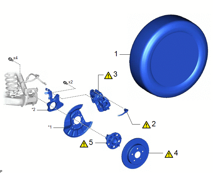
|
Procedure |
Part Name Code |
.png) |
.png) |
.png) |
|
|---|---|---|---|---|---|
|
1 |
REAR WHEEL |
- |
- |
- |
- |
|
2 |
NO. 2 PARKING BRAKE WIRE ASSEMBLY |
890C0A |
|
- |
- |
|
3 |
REAR DISC BRAKE CALIPER ASSEMBLY |
- |
|
- |
- |
|
4 |
REAR DISC |
42431 |
|
- |
- |
|
5 |
REAR AXLE HUB AND BEARING ASSEMBLY |
42450B |
|
- |
- |
|
*1 |
REAR DISC BRAKE DUST COVER SUB-ASSEMBLY |
*2 |
REAR CALIPER SUPPORT BRACKET |
CAUTION / NOTICE / HINT
HINT:
- Use the same procedure for the RH side and LH side.
- The following procedure is for the LH side.
PROCEDURE
1. REMOVE REAR WHEEL
Click here .gif)
2. DISCONNECT NO. 2 PARKING BRAKE WIRE ASSEMBLY
|
|
Click here |
3. SEPARATE REAR DISC BRAKE CALIPER ASSEMBLY
|
|
Click here |
4. REMOVE REAR DISC
|
|
Click here |
5. REMOVE REAR AXLE HUB AND BEARING ASSEMBLY
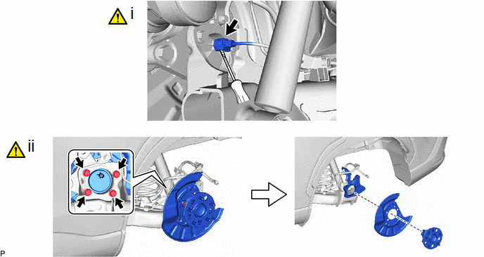
(1) Using a screwdriver with its tip wrapped with protective tape, disconnect the No. 2 parking brake wire assembly connector from the rear axle hub and bearing assembly.
NOTICE:
- Be careful not to damage the rear axle hub and bearing assembly or connector cover.
- Remove any dirt or foreign matter on and around the connector before performing this step.
- Do not allow water, oil or dirt to enter the connector.
(2) Remove the 4 bolts, rear axle hub and bearing assembly, rear disc brake dust cover sub-assembly and rear caliper support bracket from the rear axle beam assembly.
NOTICE:
- Do not drop the rear axle hub and bearing assembly and rear caliper support bracket.
- Use wire or an equivalent tool to keep the rear caliper support bracket from hanging by the rear flexible hose and brake tube.
- Be careful not to damage the speed sensor rotor or contact surfaces.
- Do not allow foreign matter to contact the speed sensor rotor or contact surfaces.


