Toyota Corolla Cross Owners & Service Manuals

Toyota Corolla Cross: On-vehicle Inspection

ON-VEHICLE INSPECTION

CAUTION / NOTICE / HINT

HINT:

  • Use the same procedure for the RH side and LH side.
  • The following procedure is for the LH side.

PROCEDURE

1. REMOVE REAR WHEEL

Click here

2. DISCONNECT NO. 2 PARKING BRAKE WIRE ASSEMBLY

Click here

3. SEPARATE REAR FLEXIBLE HOSE

Click here

4. SEPARATE REAR DISC BRAKE CALIPER ASSEMBLY

Click here

5. REMOVE REAR DISC

Click here

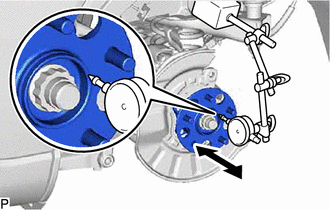
6. INSPECT REAR AXLE HUB BEARING LOOSENESS

(a) Using a dial indicator with magnetic base, check for looseness near the center of the rear axle hub.

Maximum Looseness:

0.05 mm (0.00197 in.)

NOTICE:

  • Ensure that the dial indicator is set perpendicular to the measurement surface.
  • Keep the magnet of the dial indicator away from the rear skid control sensor.

(1) If the looseness exceeds the maximum, replace the rear axle hub and bearing assembly.

7. INSPECT REAR AXLE HUB RUNOUT

(a) Using a dial indicator with magnetic base, check for runout on the surface of the rear axle hub outside the rear axle hub bolts.

Maximum Runout:

0.07 mm (0.00276 in.)

NOTICE:

  • Ensure that the dial indicator is set perpendicular to the measurement surface.
  • Make sure to install the tip of the dial indicator towards the outside of the rear axle hub bolts.
  • Keep the magnet of the dial indicator away from the rear skid control sensor.

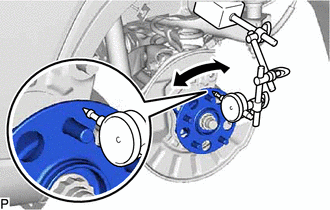
(b) If the runout exceeds the maximum, replace the rear axle hub and bearing assembly.

8. INSTALL REAR DISC

Click here

9. INSTALL REAR DISC BRAKE CALIPER ASSEMBLY

Click here

10. INSTALL REAR FLEXIBLE HOSE

Click here

11. CONNECT NO. 2 PARKING BRAKE WIRE ASSEMBLY

Click here

12. INSTALL REAR WHEEL

Click here

    READ NEXT:

     Removal

    REMOVAL CAUTION / NOTICE / HINT COMPONENTS (REMOVAL) Procedure Part Name Code 1 REAR WHEEL - -

     Installation

    INSTALLATION CAUTION / NOTICE / HINT COMPONENTS (INSTALLATION) Procedure Part Name Code 1 REAR AXLE HUB AND BEARING ASS

     Rear Axle Hub Bolt (for 2wd)

    Components COMPONENTS ILLUSTRATION *1 REAR AXLE HUB BOLT *2 REAR DISC BRAKE CALIPER ASSEMBLY *3 REAR DISC *4

    SEE MORE:

     Ultrasonic Sensor (Front Left Center) Component Internal Failure (C1AE296)

    DESCRIPTION The front center ultrasonic sensor (FLC sensor) is installed on the front bumper. The clearance warning ECU assembly detects obstacles based on signals it receives from the front center ultrasonic sensor (FLC sensor). If an open circuit or other malfunction occurs in the front cen

     Terminals Of Ecu

    TERMINALS OF ECU CHECK POWER STEERING ECU ASSEMBLY *a Component without harness connected (Power Steering ECU Assembly) - - (a) Measure the voltage and resistance according to the value(s) in the table below. NOTICE: When the EPS warni

    © 2020-2026 Copyright www.tcorollacross.com PT NL