
Toyota Corolla Cross: Removal
REMOVAL
CAUTION / NOTICE / HINT
COMPONENTS (REMOVAL)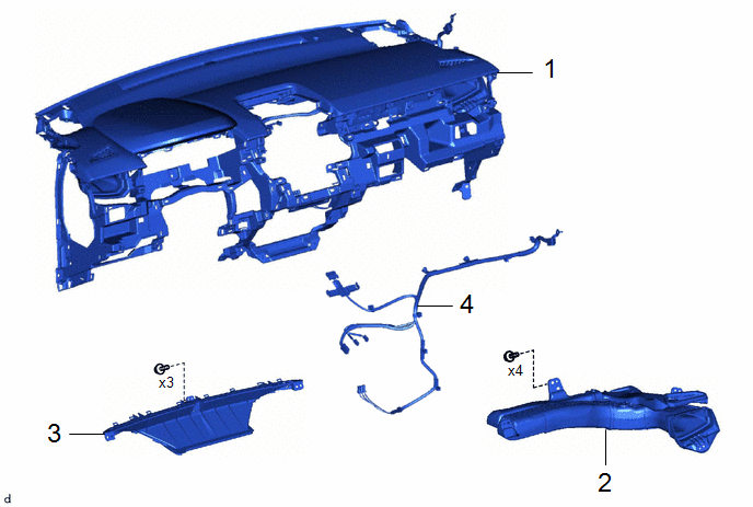
|
Procedure |
Part Name Code |
.png) |
.png) |
.png) |
|
|---|---|---|---|---|---|
|
1 |
INSTRUMENT PANEL SAFETY PAD ASSEMBLY |
- |
- |
- |
- |
|
2 |
NO. 2 HEATER TO REGISTER DUCT SUB-ASSEMBLY |
55085 |
- |
- |
- |
|
3 |
DEFROSTER NOZZLE ASSEMBLY |
55950G |
- |
- |
- |
|
4 |
ANTENNA CORD SUB-ASSEMBLY |
86101 |
- |
- |
- |
CAUTION / NOTICE / HINT
CAUTION:
Some of these service operations affect the SRS airbag system. Read the precautionary notices concerning the SRS airbag system before servicing.
.png)
Click here .gif)
HINT:
When the cable is disconnected/reconnected to the auxiliary battery terminal, systems temporarily stop operating. However, each system has a function that completes learning the first time the system is used.
- Learning completes when vehicle is driven
Effect/Inoperative Function When Necessary Procedures are not Performed
Necessary Procedures
Link
*1: for Gasoline Model Front Camera System
Drive the vehicle straight ahead at 15 km/h (10 mph) or more for 1 second or more.
Stop and start system*1
Drive the vehicle until stop and start control is permitted (approximately 5 to 60 minutes)
- Learning completes when vehicle is operated normally
Effect/Inoperative Function When Necessary Procedures are not Performed
Necessary Procedures
Link
Power door lock control system
- Back door opener
Perform door unlock operation with door control switch or electrical key transmitter sub-assembly switch.
Power back door system
Fully close the back door by hand.
HINT:
Initialization is not necessary if the above procedures are performed while the back door is closed.
Air conditioning system
After the ignition switch is turned to ON, the servo motor standard position is recognized.
-
PROCEDURE
1. REMOVE INSTRUMENT PANEL SAFETY PAD ASSEMBLY
Click here
2. REMOVE NO. 2 HEATER TO REGISTER DUCT SUB-ASSEMBLY
Click here
3. REMOVE DEFROSTER NOZZLE ASSEMBLY
Click here
4. REMOVE ANTENNA CORD SUB-ASSEMBLY
Click here


