Toyota Corolla Cross: Relay
On-vehicle Inspection
ON-VEHICLE INSPECTION
PROCEDURE
1. INSPECT HEADLIGHT RELAY LH
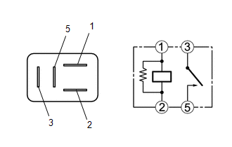
(a) Check the operation of the headlight relay LH.
| (1) Measure the resistance according to the value(s) in the table below.
Standard Resistance: |
Tester Connection | Condition |
Specified Condition | |
3 - 5 | Voltage not applied between terminals 1 and 2 |
10 kΩ or higher | |
3 - 5 | Voltage applied between terminals 1 and 2 |
Below 1 Ω | If the result is not as specified, replace the headlight relay LH. |
|
2. INSPECT HEADLIGHT RELAY RH
(a) Check the operation of the headlight relay RH.
| (1) Measure the resistance according to the value(s) in the table below.
Standard Resistance: |
Tester Connection | Condition |
Specified Condition | |
3 - 5 | Voltage not applied between terminals 1 and 2 |
10 kΩ or higher | |
3 - 5 | Voltage applied between terminals 1 and 2 |
Below 1 Ω | If the result is not as specified, replace the headlight relay RH. |
|
3. INSPECT FOG LIGHT RELAY
(a) Check the operation of the fog light relay.
| (1) Measure the resistance according to the value(s) in the table below.
Standard Resistance: |
Tester Connection | Condition |
Specified Condition | |
3 - 5 | Voltage not applied between terminals 1 and 2 |
10 kΩ or higher | |
3 - 5 | Voltage applied between terminals 1 and 2 |
Below 1 Ω | If the result is not as specified, replace the fog light relay. |
|
4. INSPECT HEADLIGHT DIMMER RELAY
(a) Check the operation of the headlight dimmer relay.
| (1) Measure the resistance according to the value(s) in the table below.
Standard Resistance: |
Tester Connection | Condition |
Specified Condition | |
3 - 5 | Voltage not applied between terminals 1 and 2 |
10 kΩ or higher | |
3 - 5 | Voltage applied between terminals 1 and 2 |
Below 1 Ω | If the result is not as specified, replace the headlight dimmer relay. |
|
READ NEXT:
REMOVAL CAUTION / NOTICE / HINT COMPONENTS (REMOVAL)
Procedure Part Name Code
1 OUTER MIRROR COVER
87945 -
- -
2 OUTER MIRROR BEZEL
- -
INSPECTION PROCEDURE 1. INSPECT SIDE TURN SIGNAL LIGHT ASSEMBLY LH
(a) Check that the side turn signal light assembly LH.
(1) Apply auxiliary battery voltage to the side turn signal light assemb
SEE MORE:
DESCRIPTION When the drive mode select switch (combination switch assembly) is operated, a switch signal is sent to the hybrid vehicle control ECU and the hybrid vehicle control ECU changes the drive mode. WIRING DIAGRAM
PROCEDURE
1. READ VALUE USING GTS (CAN BUS CHECK)
Cl
REASSEMBLY CAUTION / NOTICE / HINT COMPONENTS (REASSEMBLY)
Procedure Part Name Code
1 REAR BUMPER REINFORCEMENT SUB-ASSEMBLY
52023 -
- -
2 REAR BUMPER UPPER RETAINER LH
52563A -
- -
3 REAR BUMPER UPPER RETAINER RH
52