
Toyota Corolla Cross: Reassembly
REASSEMBLY
CAUTION / NOTICE / HINT
COMPONENTS (REASSEMBLY)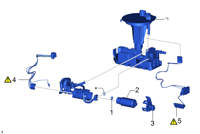
|
Procedure | Part Name Code |
.png) |
.png) |
 |
|---|---|---|---|---|---|
|
1 | FUEL PUMP SPACER |
23225A | - |
- | - |
|
2 | FUEL PUMP |
23221 | - |
- | - |
|
3 | NO. 2 FUEL SUCTION SUPPORT |
77175 | - |
- | - |
|
4 | WIRE HARNESS |
77785 |
|
- | - |
|
5 | FUEL SENDER GAUGE ASSEMBLY |
83320 |
|
- | - |
|
*1 | FUEL SUCTION PLATE SUB-ASSEMBLY |
- | - |
|
● | Non-reusable part |
- | - |
NOTICE:
Perform "Inspection After Repair" after replacing the fuel pump.
Click here .gif)
PROCEDURE
1. INSTALL FUEL PUMP SPACER
2. INSTALL FUEL PUMP
3. INSTALL NO. 2 FUEL SUCTION SUPPORT
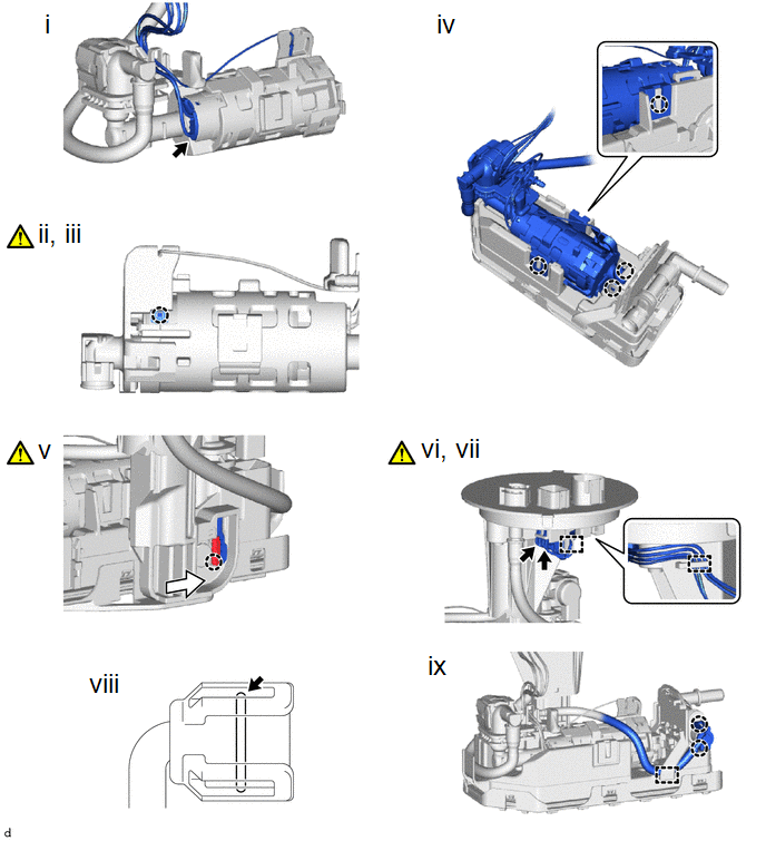
4. INSTALL WIRE HARNESS
.png) |
Fuel Pump Harness Connector |
.png) |
Slide |
(1) Connect the fuel pump harness connector.
(2) Engage the claw to connect the fuel pump harness.
NOTICE:
- Securely engage the claw.
- Make sure that there is no foreign matter between the fuel pump and the ground terminal of the fuel pump harness.
- Make sure that the ground terminal of the fuel pump harness is securely connected to the fuel pump body.
(3) Check the connection state of the fuel pump harness.Measure the resistance according to the value(s) in the table below.
Standard Resistance:
|
Tester Connection | Condition |
Specified Condition |
|---|---|---|
|
Fuel pump body - Ground terminal of the fuel pump harness |
Always | Below 50 Ω |
If the result is not as specified, reconnect the fuel pump harness to the fuel pump so that theground terminal of the fuel pump harness is securely connected to the fuel pump body.
(4) Engage the 4 claws to install the fuel suction plate sub-assembly to the fuel sub-tank subassembly.
(5) Align the protrusion of the fuel sub-tank sub-assembly with the installation hole of the fuel suction plate sub-assembly and then slide the fuel suction plate sub-assembly to install the fuel sub-tank sub-assembly.
(6) Connect the 2 fuel pump harness connectors.
(7) Engage the clamp to connect the fuel pump harness to the fuel suction plate sub-assembly.
NOTICE:
- Do not damage the wire harness.
- When engaging each wire harness to the clamp, engage one wire at a time.
(8) Install the O-ring to the fuel suction tube.
(9) Attach the 2 claws and 2 clamps and connect the tube to the fuel sub-tank subassembly.
5. INSTALL FUEL SENDER GAUGE ASSEMBLY
|
|
Click here |


