Toyota Corolla Cross: Power Back Door Warning Buzzer
Removal
REMOVAL
CAUTION / NOTICE / HINT
COMPONENTS (REMOVAL)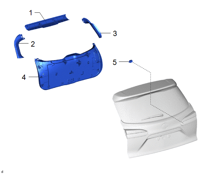
|
Procedure | Part Name Code |
.png) |
.png) |
 |
|---|---|---|---|---|---|
|
1 | BACK DOOR TRIM UPPER PANEL ASSEMBLY |
64790B | - |
- | - |
|
2 | BACK DOOR SIDE GARNISH LH |
67938A | - |
- | - |
|
3 | BACK DOOR SIDE GARNISH RH |
67937B | - |
- | - |
|
4 | BACK DOOR TRIM PANEL ASSEMBLY |
64780A | - |
- | - |
|
5 | POWER BACK DOOR WARNING BUZZER |
89747E | - |
- | - |
PROCEDURE
1. REMOVE BACK DOOR TRIM UPPER PANEL ASSEMBLY
Click here
.gif)
2. REMOVE BACK DOOR SIDE GARNISH LH
Click here
3. REMOVE BACK DOOR SIDE GARNISH RH
(a) Use the same procedure as for the LH side.
4. REMOVE BACK DOOR TRIM PANEL ASSEMBLY
Click here
5. REMOVE POWER BACK DOOR WARNING BUZZER

Installation
INSTALLATION
CAUTION / NOTICE / HINT
COMPONENTS (INSTALLATION)
|
Procedure | Part Name Code |
.png) |
.png) |
 |
|---|---|---|---|---|---|
|
1 | POWER BACK DOOR WARNING BUZZER |
89747E | - |
- | - |
|
2 | BACK DOOR TRIM PANEL ASSEMBLY |
64780A | - |
- | - |
|
3 | BACK DOOR SIDE GARNISH LH |
67938A | - |
- | - |
|
4 | BACK DOOR SIDE GARNISH RH |
67937B | - |
- | - |
|
5 | BACK DOOR TRIM UPPER PANEL ASSEMBLY |
64790B | - |
- | - |
PROCEDURE
1. INSTALL POWER BACK DOOR WARNING BUZZER
2. INSTALL BACK DOOR TRIM PANEL ASSEMBLY
3. INSTALL BACK DOOR SIDE GARNISH LH
4. INSTALL BACK DOOR SIDE GARNISH RH
5. INSTALL BACK DOOR TRIM UPPER PANEL ASSEMBLY


