Toyota Corolla Cross: Parts Location
PARTS LOCATION
ILLUSTRATION
|
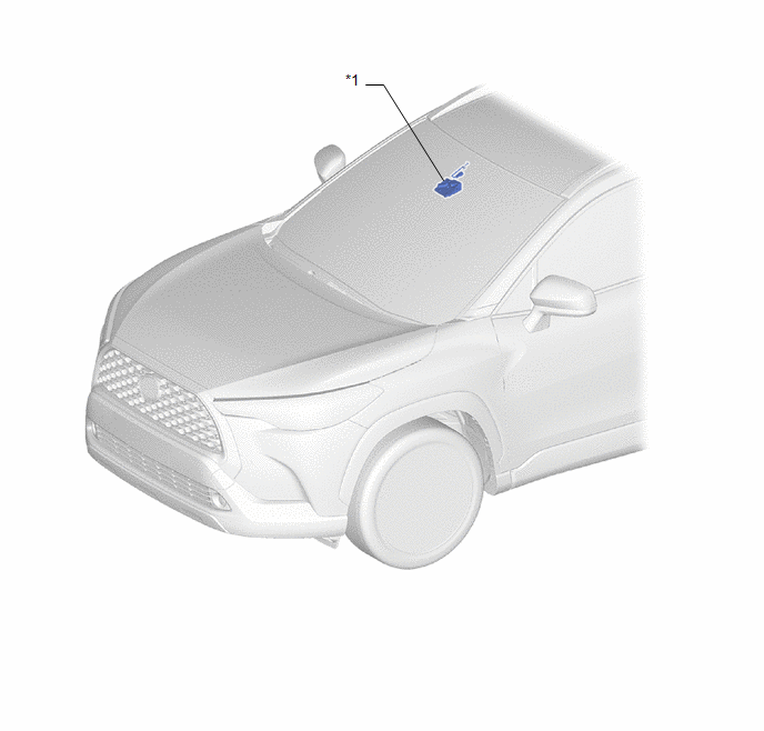
*1 | FORWARD RECOGNITION CAMERA |
- | - |
ILLUSTRATION
|
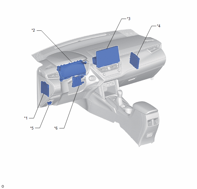
*1 | MAIN BODY ECU (MULTIPLEX NETWORK BODY ECU) |
*2 | COMBINATION METER ASSEMBLY |
|
*3 | RADIO AND DISPLAY RECEIVER ASSEMBLY |
*4 | CERTIFICATION ECU (SMART KEY ECU ASSEMBLY) |
|
*5 | DLC3 |
*6 | AIR CONDITIONING AMPLIFIER ASSEMBLY |
ILLUSTRATION
|
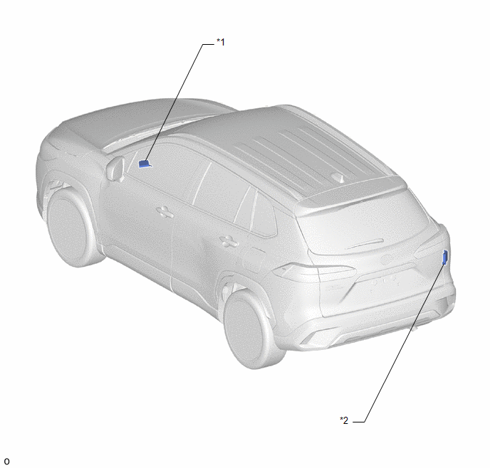
*1 | CLEARANCE WARNING ECU ASSEMBLY |
*2 | BLIND SPOT MONITOR SENSOR RH (B) |
READ NEXT:
CAUTION / NOTICE / HINT
HINT:
Use the following procedure to troubleshoot the my settings system.
*: Use the GTS.
PROCEDURE
1. VEHICLE BROUGHT TO WORKSHOP
NEXT
REGISTRATION PROCEDURE 1. ASSIGNING SETTINGS
NOTICE: Make sure to complete driver registration before assigning settings.
Procedure Steps
1. Assigning settings (electrical key transm
SEE MORE:
DESCRIPTION The certification ECU (smart key ECU assembly) generates a request signal and transmits the signal to the electrical key antenna (outside luggage compartment). For the electrical key antenna (outside luggage compartment) to detect when the electrical key transmitter sub-assembly is broug
DESCRIPTION
The battery state sensor assembly detects the voltage, current and temperature
of the auxiliary battery. The auxiliary battery state sensor assembly calculates
State of Charge (SOC) based on the voltage and current of the auxiliary battery
and sends it to the ECM. Based on the sig


