Toyota Corolla Cross: Parts Location
Toyota Corolla Cross (2022-2026) Service Manual / Vehicle Exterior / Door / Hatch / Power Back Door System / Parts Location
PARTS LOCATION
ILLUSTRATION
|
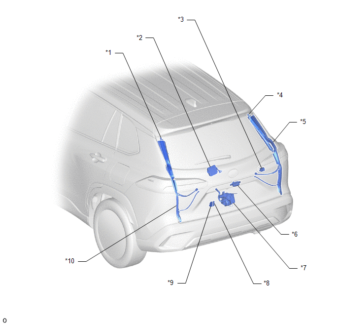
*1 | POWER BACK DOOR UNIT ASSEMBLY SET LH |
*2 | MULTIPLEX NETWORK DOOR ECU |
|
*3 | POWER BACK DOOR WARNING BUZZER |
*4 | POWER BACK DOOR UNIT ASSEMBLY SET RH |
|
*5 | POWER BACK DOOR SENSOR ASSEMBLY RH |
*6 | BACK DOOR OPENER SWITCH ASSEMBLY |
|
*7 | BACK DOOR LOCK WITH COURTESY LIGHT SWITCH ASSEMBLY |
*8 | BACK DOOR CONTROL SWITCH |
|
*9 | NO. 1 POWER BACK DOOR CONTROL SWITCH |
*10 | POWER BACK DOOR SENSOR ASSEMBLY LH |
ILLUSTRATION
|
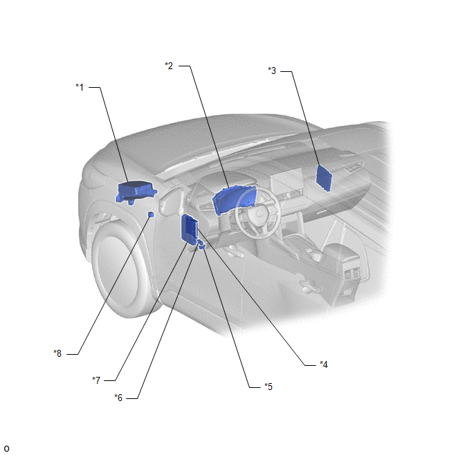
*1 | NO. 1 ENGINE ROOM RELAY BLOCK - PBD FUSE | *2 |
COMBINATION METER ASSEMBLY |
|
*3 | CERTIFICATION ECU (SMART KEY ECU ASSEMBLY) |
*4 | MAIN BODY ECU (MULTIPLEX NETWORK BODY ECU) |
|
*5 | DLC3 |
*6 | POWER BACK DOOR CONTROL SWITCH |
|
*7 | POWER DISTRIBUTION BOX ASSEMBLY - ECU-IG1 NO. 4 FUSE - ECU-B NO. 2 FUSE |
*8 | WIRELESS DOOR LOCK BUZZER |


