Toyota Corolla Cross: Parts Location
PARTS LOCATION
ILLUSTRATION
|
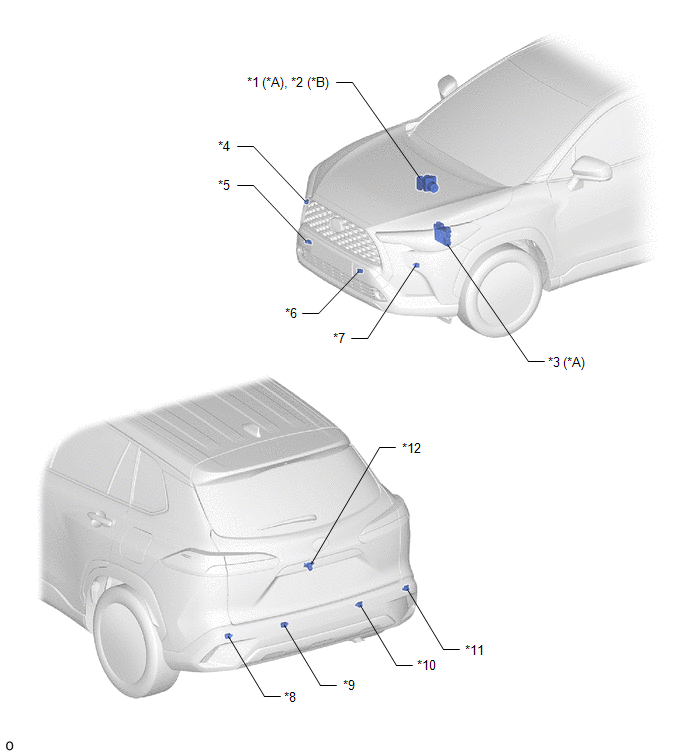
*A |
for Gasoline Model |
*B |
for HEV Model |
|
*1 |
BRAKE ACTUATOR ASSEMBLY (SKID CONTROL ECU) |
*2 |
BRAKE ACTUATOR ASSEMBLY (NO. 2 SKID CONTROL ECU) |
|
*3 |
ECM |
*4 |
FRONT CORNER ULTRASONIC SENSOR (FR SENSOR) |
|
*5 |
FRONT CENTER ULTRASONIC SENSOR (FRC SENSOR) |
*6 |
FRONT CENTER ULTRASONIC SENSOR (FLC SENSOR) |
|
*7 |
FRONT CORNER ULTRASONIC SENSOR (FL SENSOR) |
*8 |
REAR CORNER ULTRASONIC SENSOR (RL SENSOR) |
|
*9 |
REAR CENTER ULTRASONIC SENSOR (RLC SENSOR) |
*10 |
REAR CENTER ULTRASONIC SENSOR (RRC SENSOR) |
|
*11 |
REAR CORNER ULTRASONIC SENSOR (RR SENSOR) |
*12 |
REAR TELEVISION CAMERA ASSEMBLY |
ILLUSTRATION
|
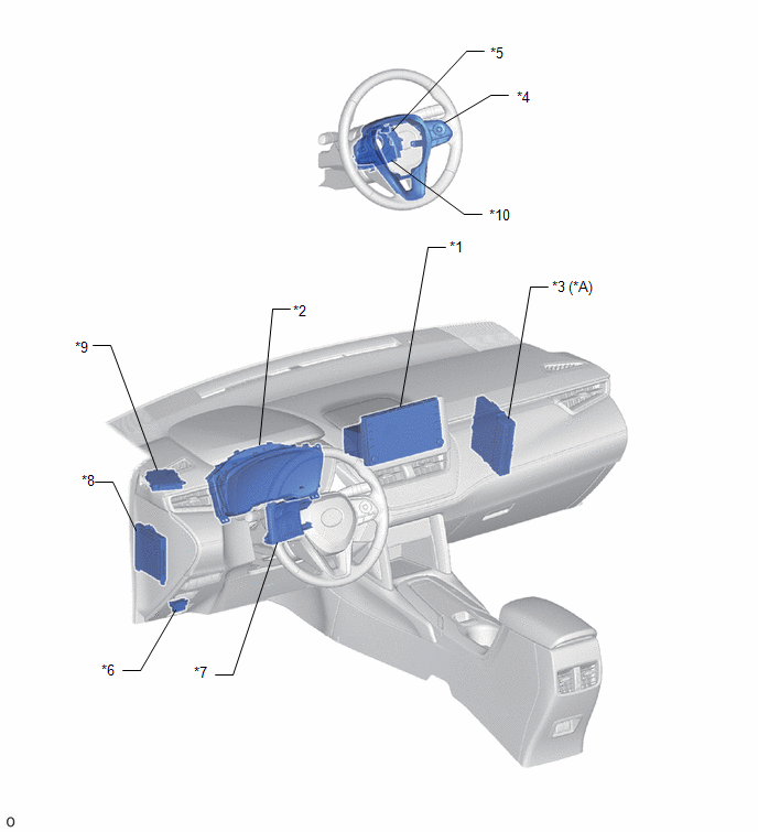
*A |
for HEV Model |
- |
- |
|
*1 |
RADIO AND DISPLAY RECEIVER ASSEMBLY |
*2 |
COMBINATION METER ASSEMBLY |
|
*3 |
HYBRID VEHICLE CONTROL ECU |
*4 |
STEERING PAD SWITCH ASSEMBLY |
|
*5 |
SPIRAL CABLE SUB-ASSEMBLY |
*6 |
DLC3 |
|
*7 |
AIR CONDITIONING AMPLIFIER ASSEMBLY |
*8 |
MAIN BODY ECU (MULTIPLEX NETWORK BODY ECU) |
|
*9 |
CLEARANCE WARNING ECU ASSEMBLY |
*10 |
STEERING SENSOR |


