Toyota Corolla Cross: Installation
INSTALLATION
CAUTION / NOTICE / HINT
COMPONENTS (INSTALLATION)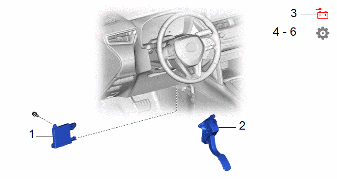
|
Procedure | Part Name Code |
.png) |
.png) |
 |
|---|---|---|---|---|---|
|
1 | AIR CONDITIONING AMPLIFIER ASSEMBLY |
88650N | - |
- | - |
|
2 | ACCELERATOR PEDAL SENSOR ASSEMBLY |
78110K | - |
- | - |
|
3 | CONNECT CABLE TO NEGATIVE AUXILIARY BATTERY TERMINAL |
- | - |
- | - |
|
4 | PERFORM REGISTRATION |
- | - |
- |
|
|
5 | INITIALIZATION AFTER RECONNECTING AUXILIARY BATTERY TERMINAL |
- | - |
- |
|
|
6 | INITIALIZATION SERVO MOTOR |
- | - |
- |
|
PROCEDURE
1. INSTALL AIR CONDITIONING AMPLIFIER ASSEMBLY
2. INSTALL ACCELERATOR PEDAL SENSOR ASSEMBLY
- for M20A-FKS:
Click here
.gif)
- for M20A-FXS:
Click here
3. CONNECT CABLE TO NEGATIVE AUXILIARY BATTERY TERMINAL
- for M20A-FKS:
Click here
- for M20A-FXS:
Click here
4. PERFORM REGISTRATION (for Gasoline Model)
Click here
5. INITIALIZATION AFTER RECONNECTING AUXILIARY BATTERY TERMINAL
HINT:
When disconnecting and reconnecting the auxiliary battery, there is an automatic learning function that completes learning when the respective system is used.
Click here
6. INITIALIZATION SERVO MOTOR
- for Gasoline Model with Manual Air Conditioning System:
Click here
- for Gasoline Model with Automatic Air Conditioning System:
Click here
- for HEV Model:
Click here


