Toyota Corolla Cross: Installation
INSTALLATION
CAUTION / NOTICE / HINT
COMPONENTS (INSTALLATION)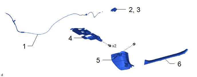
|
Procedure | Part Name Code |
.png) |
.png) |
 |
|---|---|---|---|---|---|
|
1 | HOOD LOCK CONTROL CABLE ASSEMBLY |
53630 | - |
- | - |
|
2 | INSTALL HOOD LOCK CONTROL LEVER SUB-ASSEMBLY |
53601 | - |
- | - |
|
3 | CONNECT HOOD LOCK CONTROL LEVER SUB-ASSEMBLY |
53601 | - |
- | - |
|
4 | NO. 1 INSTRUMENT PANEL UNDER COVER SUB-ASSEMBLY |
55606 | - |
- | - |
|
5 | COWL SIDE TRIM SUB-ASSEMBLY LH |
62112A | - |
- | - |
|
6 | FRONT DOOR SCUFF PLATE LH |
67914B | - |
- | - |
|
Procedure | Part Name Code |
|
|
| |
|---|---|---|---|---|---|
|
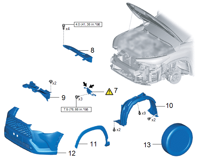
7 | HOOD LOCK ASSEMBLY |
53510 |
|
- | - |
|
8 | INLET NO. 1 AIR CLEANER |
17751 | - |
- | - |
|
9 | NO. 1 RADIATOR TO SUPPORT SEAL |
16561C | - |
- | - |
|
10 | FRONT FENDER LINER LH |
53876A | - |
- | - |
|
11 | FRONT FENDER MOULDING SUB-ASSEMBLY LH |
75602A | - |
- | - |
|
12 | FRONT BUMPER ASSEMBLY |
- | - |
- | - |
|
13 | FRONT WHEEL LH |
- | - |
- | - |
.png) |
N*m (kgf*cm, ft.*lbf): Specified torque |
.png) |
MP grease |
PROCEDURE
1. INSTALL HOOD LOCK CONTROL CABLE ASSEMBLY
2. INSTALL HOOD LOCK CONTROL LEVER SUB-ASSEMBLY
3. CONNECT HOOD LOCK CONTROL LEVER SUB-ASSEMBLY
4. INSTALL NO. 1 INSTRUMENT PANEL UNDER COVER SUB-ASSEMBLY
5. INSTALL COWL SIDE TRIM SUB-ASSEMBLY LH
6. INSTALL FRONT DOOR SCUFF PLATE LH
7. INSTALL HOOD LOCK WITH COURTESY LIGHT SWITCH ASSEMBLY

.png) |
MP Grease | - |
- |
(1) Apply MP grease to the sliding parts of the hood lock with courtesy light switch assembly.
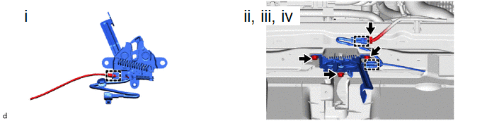
(1) Engage the guide and connect the hood lock control cable assembly to the hood lock with courtesy light switch assembly.
(2) Install the hood lock with courtesy light switch assembly with the 3 bolts.
Torque:
7.5 N·m {76 kgf·cm, 66 in·lbf}
(3) Engage the clamps.
(4) Connect the connector.
8. INSTALL INLET NO. 1 AIR CLEANER
Click here
.gif)
9. INSTALL NO. 1 RADIATOR TO SUPPORT SEAL
10. INSTALL FRONT FENDER LINER LH
11. INSTALL FRONT FENDER MOULDING SUB-ASSEMBLY LH
Click here
12. INSTALL FRONT BUMPER ASSEMBLY
- for Sport Package:
Click here
- except Sport Package:
Click here
13. INSTALL FRONT WHEEL LH
Click here


