Toyota Corolla Cross: Installation
INSTALLATION
CAUTION / NOTICE / HINT
COMPONENTS (INSTALLATION)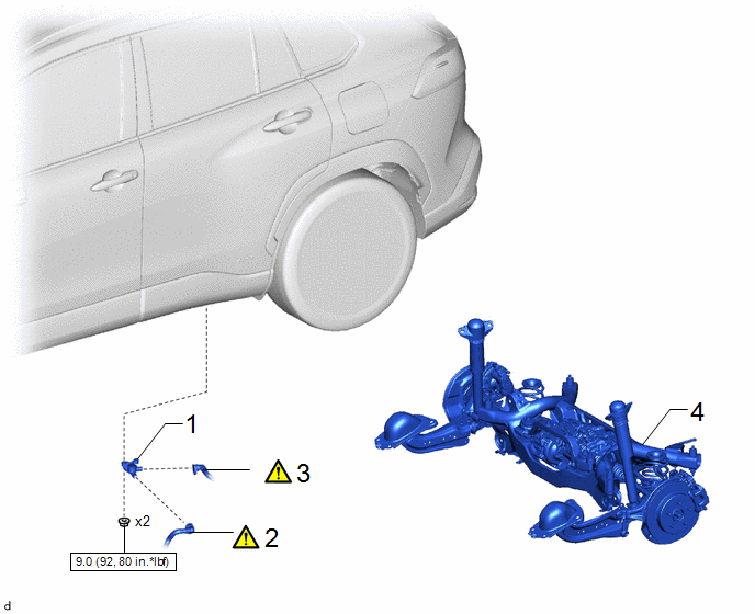
|
Procedure | Part Name Code |
.png) |
.png) |
 |
|---|---|---|---|---|---|
|
1 | FUEL VAPOR CONTAINMENT VALVE (FUEL TANK SOLENOID MAIN VALVE ASSEMBLY) |
77070A | - |
- | - |
|
2 | FUEL TANK VENT HOSE SUB-ASSEMBLY |
77404A |
|
- | - |
|
3 | NO. 2 FUEL TANK VENT HOSE SUB-ASSEMBLY |
77404B |
|
- | - |
|
4 | REAR SUSPENSION MEMBER SUB-ASSEMBLY |
51206A | - |
- | - |
.png) |
N*m (kgf*cm, ft.*lbf): Specified torque |
- | - |
PROCEDURE
1. INSTALL FUEL VAPOR CONTAINMENT VALVE (FUEL TANK SOLENOID MAIN VALVE ASSEMBLY)
Torque:
9.0 N·m {92 kgf·cm, 80 in·lbf}
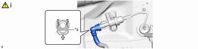
2. CONNECT FUEL TANK VENT HOSE SUB-ASSEMBLY
|
*a | Retainer |
- | - |
.png) |
Push in | - |
- |
(1) Connect the fuel tank vent hose sub-assembly to the fuel vapor containment valve (fuel tank solenoid main valve assembly).
Click here .gif)
NOTICE:
- Check that there are no scratches or foreign matter around the connecting parts of the fuel tank vent hose sub-assembly and fuel vapor containment valve (fuel tank solenoid main valve assembly) before performing this work.
- After connecting the fuel tank vent hose sub-assembly, check that the fuel tank vent hose sub-assembly are securely connected by pulling on the fuel tank vent hose sub-assembly.
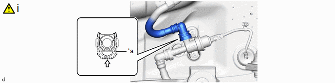
3. CONNECT NO. 2 FUEL TANK VENT HOSE SUB-ASSEMBLY
|
*a | Retainer |
- | - |
|
|
Push in | - |
- |
(1) Connect the No. 2 fuel tank vent hose sub-assembly to the fuel vapor containment valve (fuel tank solenoid main valve assembly).
Click here
NOTICE:
- Check that there are no scratches or foreign matter around the connecting parts of the No. 2 fuel tank vent hose sub-assembly and fuel vapor containment valve (fuel tank solenoid main valve assembly) before performing this work.
- After connecting the No. 2 fuel tank vent hose sub-assembly, check that the No. 2 fuel tank vent hose sub-assembly are securely connected by pulling on the No. 2 fuel tank vent hose sub-assembly.
4. INSTALL REAR SUSPENSION MEMBER SUB-ASSEMBLY
Click here


