Toyota Corolla Cross: Installation
INSTALLATION
CAUTION / NOTICE / HINT
|
Procedure | Part Name Code |
.png) |
.png) |
 |
|---|---|---|---|---|---|
|
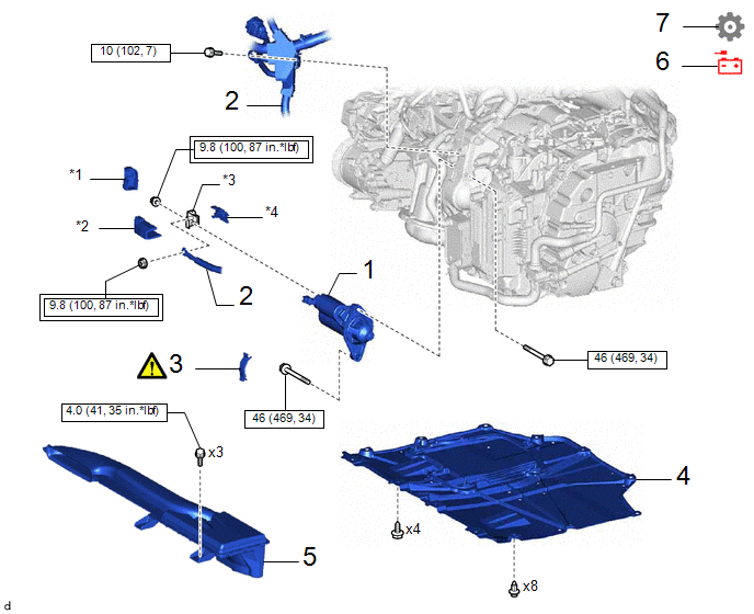
1 | STARTER ASSEMBLY |
28100 | - |
- | - |
|
2 | ENGINE WIRE |
82121 | - |
- | - |
|
3 | FLYWHEEL HOUSING SIDE COVER |
11363A |
|
- | - |
|
4 | NO. 1 ENGINE UNDER COVER ASSEMBLY |
51410 | - |
- | - |
|
5 | AIR CLEANER INLET NO. 1 |
17751 | - |
- | - |
|
6 | NEGATIVE AUXILIARY BATTERY TERMINAL |
- | - |
- | - |
|
7 | INITIALIZATION AFTER RECONNECTING AUXILIARY BATTERY TERMINAL |
- | - |
- |
|
|
*1 | COVER A |
*2 | COVER B |
|
*3 | STARTER TERMINAL |
*4 | BASE |
.png) |
Tightening torque for "Major areas involving basic vehicle performance such as moving/turning/stopping" : N*m (kgf*cm, ft.*lbf) |
.png) |
N*m (kgf*cm, ft.*lbf): Specified torque |
PROCEDURE
1. INSTALL STARTER ASSEMBLY
Torque:
for Bolt :
9.8 N·m {100 kgf·cm, 87 in·lbf}
for Nut :
46 N·m {469 kgf·cm, 34 ft·lbf}
2. INSTALL ENGINE WIRE
Torque:
for Bolt :
10 N·m {102 kgf·cm, 7 ft·lbf}
for Nut :
9.8 N·m {100 kgf·cm, 87 in·lbf}
3. INSTALL FLYWHEEL HOUSING SIDE COVER

(1) Align the protrusion with the cylinder block sub-assembly and engage the claw as shown in the illustration to install the flywheel housing side cover.
NOTICE:
- Make sure the claw makes a click sound, indicating that it fits tightly.
- Replace the flywheel housing side cover with a new one if the claw does not fit tightly or is deformed.
4. INSTALL NO. 1 ENGINE UNDER COVER ASSEMBLY
Click here
.gif)
5. INSTALL INLET NO. 1 AIR CLEANER INLET
Click here
6. CONNECT CABLE FROM NEGATIVE AUXILIARY BATTERY TERMINAL
Click here
7. INITIALIZATION AFTER RECONNECTING AUXILIARY BATTERY TERMINAL
HINT:
When disconnecting and reconnecting the auxiliary battery, there is an automatic learning function thatcompletes learning when the respective system is used.
Click here


