Toyota Corolla Cross: Starting System
Toyota Corolla Cross (2022-2026) Service Manual / Engine & Hybrid System / M20a-fks (starting) / Starting System
Parts Location
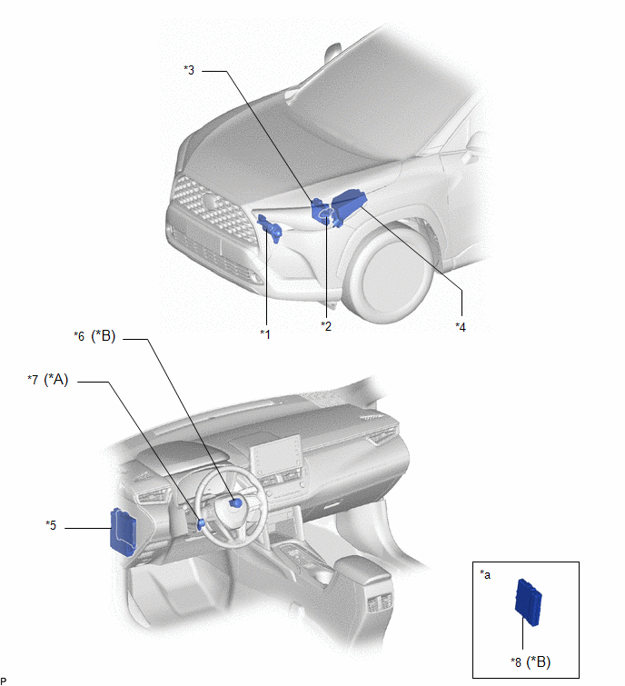
PARTS LOCATION
ILLUSTRATION
|
*A | w/o Smart Key System |
*B | w/ Smart Key System |
|
*1 | STARTER ASSEMBLY |
*2 | PARK/NEUTRAL POSITION SWITCH ASSEMBLY |
|
*3 | ECM |
*4 | NO. 1 ENGINE ROOM RELAY BLOCK AND NO. 1 JUNCTION BLOCK ASSEMBLY - J/B-B FUSE - ST RELAY - ST FUSE |
|
*5 | INSTRUMENT PANEL JUNCTION BLOCK ASSEMBLY - AM2 FUSE | *6 |
ENGINE SWITCH |
|
*7 | IGNITION OR STARTER SWITCH ASSEMBLY |
*8 | CERTIFICATION ECU (SMART KEY ECU ASSEMBLY) |
|
*a | Refer to Service Bulletin for the installation position of the parts. |
- | - |


