Toyota Corolla Cross: Installation
INSTALLATION
CAUTION / NOTICE / HINT
COMPONENTS (INSTALLATION)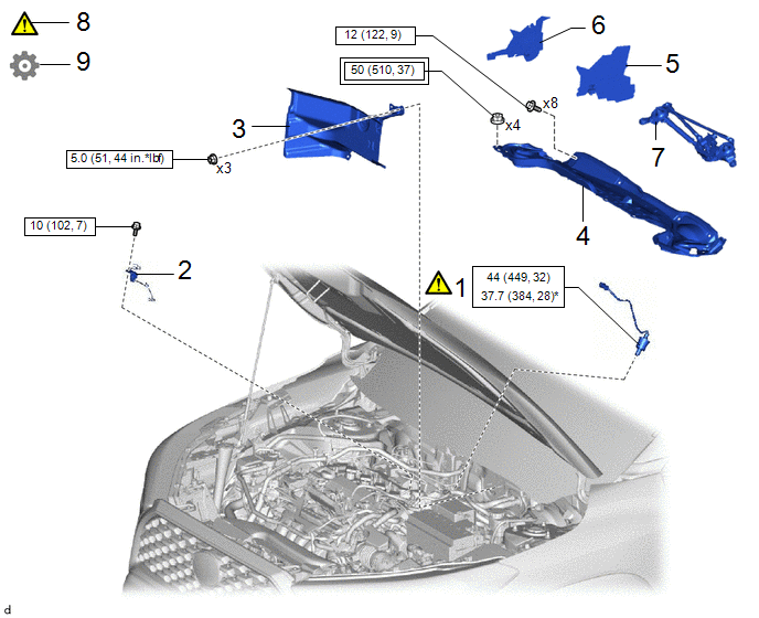
|
Procedure | Part Name Code |
.png) |
.png) |
 |
|---|---|---|---|---|---|
|
1 | AIR FUEL RATIO SENSOR |
89467B |
|
- | - |
|
2 | WIRE HARNESS CLAMP BRACKET |
- | - |
- | - |
|
3 | DASH PANEL HEAT INSULATOR |
55225C | - |
- | - |
|
4 | OUTER COWL TOP PANEL SUB-ASSEMBLY |
55701J | - |
- | - |
|
5 | NO. 1 HEATER AIR DUCT SPLASH SHIELD SEAL |
55737B | - |
- | - |
|
6 | WATER GUARD PLATE |
55734D | - |
- | - |
|
7 | WINDSHIELD WIPER MOTOR AND LINK ASSEMBLY |
- | - |
- | - |
|
8 | INSPECT FOR EXHAUST GAS LEAK |
- |
|
- | - |
|
9 | PERFORM INITIALIZATION |
- | - |
- |
|
.png) |
Tightening torque for "Major areas involving basic vehicle performance such as moving/turning/stopping" : N*m (kgf*cm, ft.*lbf) |
.png) |
N*m (kgf*cm, ft.*lbf): Specified torque |
|
* | For use with SST |
- | - |
PROCEDURE
1. INSTALL AIR FUEL RATIO SENSOR
|
|
HINT: Perform "Inspection After Repair" after replacing the air fuel ratio sensor. Click here |

|
*a | Torque Wrench Fulcrum Length |
- | - |
(1) Using SST, install the air fuel ratio sensor to the exhaust manifold (TWC: Front Catalyst).
SST: 09224-00012
Torque:
Specified tightening torque :
44 N·m {449 kgf·cm, 32 ft·lbf}
NOTICE:
If the air fuel ratio sensor has been struck or dropped, replace it.
HINT:
- Calculate the torque wrench reading when changing the fulcrum length of the torque wrench.
Click here
.gif)
- When using SST (fulcrum length of 30 mm (1.18 in.)) + torque wrench (fulcrum length of 180 mm (7.09 in.)):
37.7 N*m (384 kgf*cm, 28 ft.*lbf)
2. INSTALL WIRE HARNESS CLAMP BRACKET
Torque:
10 N·m {102 kgf·cm, 7 ft·lbf}
3. INSTALL DASH PANEL HEAT INSULATOR
Click here
4. INSTALL OUTER COWL TOP PANEL SUB-ASSEMBLY
Click here
5. INSTALL NO. 1 HEATER AIR DUCT SPLASH SHIELD SEAL
Click here
6. INSTALL WATER GUARD PLATE
Click here
7. INSTALL WINDSHIELD WIPER MOTOR AND LINK ASSEMBLY
Click here
8. INSPECT FOR EXHAUST GAS LEAK
Click here
9. PERFORM INITIALIZATION
(a) Perform "Inspection After Repair" after replacing the air fuel ratio sensor.
Click here


