Toyota Corolla Cross: Installation
INSTALLATION
CAUTION / NOTICE / HINT
COMPONENTS (INSTALLATION)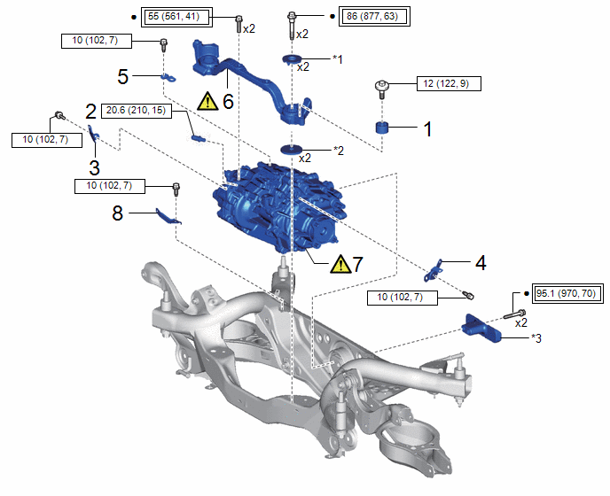
|
Procedure |
Part Name Code |
.png) |
.png) |
.png) |
|
|---|---|---|---|---|---|
|
1 |
DIFFERENTIAL DYNAMIC DAMPER |
41196B |
- |
- |
- |
|
2 |
REAR TRACTION MOTOR BREATHER PLUG |
30900T |
- |
- |
- |
|
3 |
NO. 2 WIRING HARNESS CLAMP BRACKET |
82715S |
- |
- |
- |
|
4 |
NO. 2 MOTOR CABLE BRACKET |
G1143F |
- |
- |
- |
|
5 |
NO. 3 MOTOR CABLE BRACKET |
G1143G |
- |
- |
- |
|
6 |
FRONT DIFFERENTIAL SUPPORT ASSEMBLY |
52380F |
|
- |
- |
|
7 |
REAR TRACTION MOTOR WITH TRANSAXLE ASSEMBLY |
G1050 |
|
- |
- |
|
8 |
NO. 3 WIRING HARNESS CLAMP BRACKET |
82715T |
- |
- |
- |
|
*1 |
UPPER DIFFERENTIAL MOUNT STOPPER |
*2 |
LOWER DIFFERENTIAL MOUNT STOPPER |
|
*3 |
DIFFERENTIAL MASS DAMPER |
- |
- |
.png) |
Tightening torque for "Major areas involving basic vehicle performance such as moving/turning/stopping": N*m (kgf*cm, ft.*lbf) |
.png) |
N*m (kgf*cm, ft.*lbf): Specified torque |
|
● |
Non-reusable part |
- |
- |
|
Procedure |
Part Name Code |
|
|
|
|
|---|---|---|---|---|---|
|
9 |
NO. 9 FLOOR WIRE |
8216C |
- |
- |
- |
|
10 |
REAR TRACTION MOTOR CABLE |
G1149 |
- |
- |
- |
|
11 |
PERFORM RESOLVER INITIALIZATION |
- |
|
- |
- |
|
|
N*m (kgf*cm, ft.*lbf): Specified torque |
- |
- |
PROCEDURE
1. INSTALL DIFFERENTIAL DYNAMIC DAMPER
HINT:
Perform this procedure only when replacement of the differential dynamic damper is necessary.
Torque:
12 N·m {122 kgf·cm, 9 ft·lbf}
2. INSTALL REAR TRACTION MOTOR BREATHER PLUG
HINT:
Perform this procedure only when replacement of the rear traction motor breather plug is necessary.
Torque:
20.6 N·m {210 kgf·cm, 15 ft·lbf}
3. INSTALL NO. 2 WIRING HARNESS CLAMP BRACKET
Torque:
10 N·m {102 kgf·cm, 7 ft·lbf}
4. INSTALL NO. 2 MOTOR CABLE BRACKET
Torque:
10 N·m {102 kgf·cm, 7 ft·lbf}
5. INSTALL NO. 3 MOTOR CABLE BRACKET
Torque:
10 N·m {102 kgf·cm, 7 ft·lbf}
6. TEMPORARILY TIGHTEN FRONT DIFFERENTIAL SUPPORT ASSEMBLY
(1) Temporarily install the front differential support assembly to the rear traction motor with transaxle assembly with 2 new bolts.
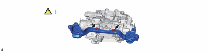
7. INSTALL REAR TRACTION MOTOR WITH TRANSAXLE ASSEMBLY
.png)
.png) |
Support Positions |
- |
- |
(1) Using an engine sling device and belts, support the rear traction motor with transaxle assembly in the position shown in the illustration.
NOTICE:
- Do not lift the rear traction motor with transaxle assembly any higher than is necessary.
- When lifting the rear traction motor with transaxle assembly, check the location of the center of gravity while lifting it.
|
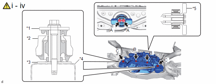
*1 |
UPPER DIFFERENTIAL MOUNT STOPPER |
*2 |
FRONT DIFFERENTIAL SUPPORT ASSEMBLY |
|
*3 |
LOWER DIFFERENTIAL MOUNT STOPPER |
*4 |
REAR SUSPENSION MEMBER SUB-ASSEMBLY |
|
*5 |
DIFFERENTIAL MASS DAMPER |
- |
- |
(1) Using 4 new bolts which are passed through the 2 upper differential mount stoppers, the 2 lower differential mount stoppers and the differential mass damper, temporarily install the rear traction motor with transaxle assembly to the rear suspension member sub-assembly.
(2) Fully tighten the 2 bolts (A).
Torque:
95.1 N·m {970 kgf·cm, 70 ft·lbf}
(3) Fully tighten the 2 bolts (B).
Torque:
55 N·m {561 kgf·cm, 41 ft·lbf}
(4) Fully tighten the 2 bolts (C).
Torque:
86 N·m {877 kgf·cm, 63 ft·lbf}
8. INSTALL NO. 3 WIRING HARNESS CLAMP BRACKET
Torque:
10 N·m {102 kgf·cm, 7 ft·lbf}
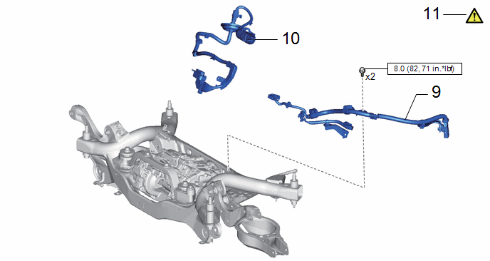
9. INSTALL NO. 9 FLOOR WIRE
Torque:
8.0 N·m {82 kgf·cm, 71 in·lbf}
10. INSTALL REAR TRACTION MOTOR CABLE
Click here .gif)
11. PERFORM RESOLVER INITIALIZATION
|
|
NOTICE: If the rear traction motor with transaxle assembly has been replaced, make sure to perform resolver learning. Click here |