Toyota Corolla Cross: Installation
INSTALLATION
CAUTION / NOTICE / HINT
COMPONENTS (INSTALLATION)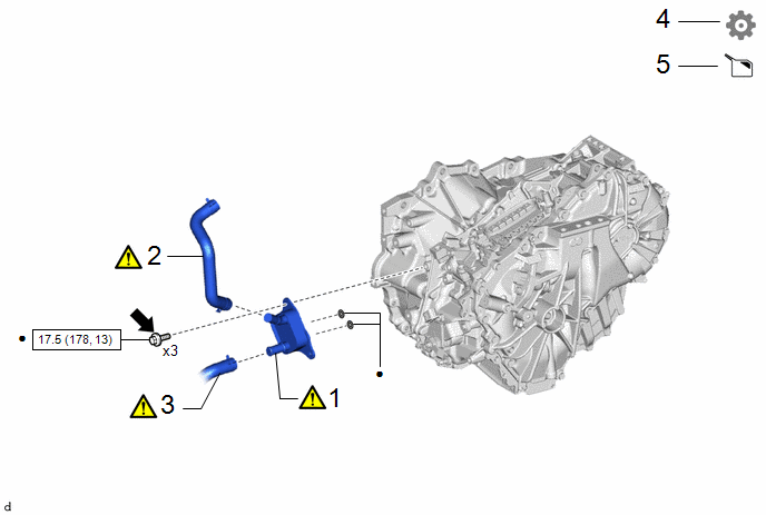
|
Procedure |
Part Name Code |
.png) |
.png) |
.png) |
|
|---|---|---|---|---|---|
|
1 |
MOTOR COOLING COOLER |
G125AA |
|
- |
- |
|
2 |
NO. 1 INVERTER COOLING OUTLET HOSE |
G922C |
|
- |
- |
|
3 |
NO. 2 INVERTER COOLING OUTLET HOSE |
G922D |
|
- |
- |
|
4 |
INSPECT HYBRID TRANSAXLE FLUID |
- |
- |
- |
|
|
5 |
HYBRID TRANSAXLE FLUID LEAK |
- |
- |
|
- |
.png) |
N*m (kgf*cm, ft.*lbf): Specified torque |
.png) |
Toyota Genuine Adhesive 1324, Three Bond 1324 or equivalent |
|
● |
Non-reusable part |
- |
- |
|
Procedure |
Part Name Code |
|
|
|
|
|---|---|---|---|---|---|
|
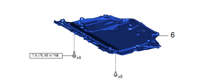
6 |
NO. 1 ENGINE UNDER COVER ASSEMBLY |
51410 |
- |
- |
- |
|
|
N*m (kgf*cm, ft.*lbf): Specified torque |
- |
- |
PROCEDURE
1. INSTALL MOTOR COOLING COOLER
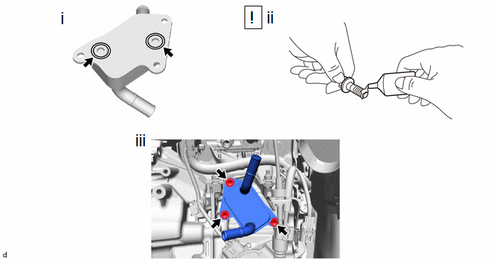
(1) Install the 2 new O-rings to the motor cooling cooler.
(2) Apply adhesive to 2 or 3 threads at the end of each of 3 new bolts.
Adhesive:
Toyota Genuine Adhesive 1324, Three Bond 1324 or equivalent
(3) Tighten the 3 bolts.
Torque:
17.5 N·m {178 kgf·cm, 13 ft·lbf}
2. INSTALL NO. 1 INVERTER COOLING OUTLET HOSE
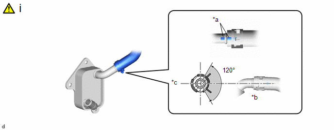
|
*a |
Paint Mark (A) |
*b |
Paint Mark (B) |
|
*c |
Center of Paint Mark |
.png) |
Claw of Clip Location |
(1) Install the No. 1 motor cooling hose to the motor cooling cooler and slide the clip to secure it.
NOTICE:
- Be careful not to deform the motor cooling cooler.
- Make sure to align the paint mark on the No. 1 motor cooling hose with the paint mark on the motor cooling cooler.
- Make sure that the claws of the clip are positioned within the area shown in the illustration.
3. INSTALL NO. 2 INVERTER COOLING OUTLET HOSE
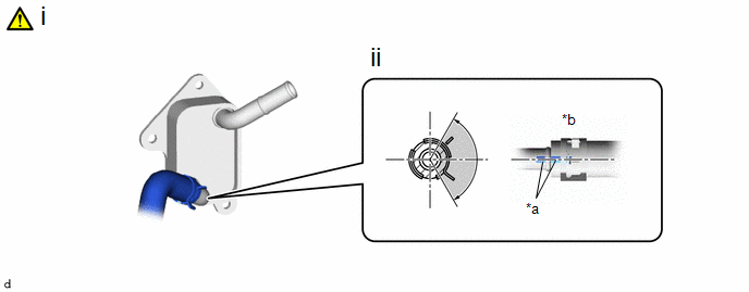
|
*a |
Paint Mark |
*b |
Center of Paint Mark |
|
|
Claw of Clip Location |
- |
- |
(1) Install the No. 2 motor cooling hose to the motor cooling cooler and slide the clip to secure it.
NOTICE:
- Be careful not to deform the motor cooling cooler.
- Make sure to align the paint mark on the No. 2 motor cooling hose with the paint mark on the motor cooling cooler.
- Make sure that the claws of the clip are positioned within the area shown in the illustration.
4. INSPECT HYBRID TRANSAXLE FLUID
Click here .gif)
5. INSPECT FOR HYBRID TRANSAXLE FLUID LEAK
6. INSTALL NO. 1 ENGINE UNDER COVER ASSEMBLY
Click here


