Toyota Corolla Cross: Installation
INSTALLATION
CAUTION / NOTICE / HINT
COMPONENTS (INSTALLATION)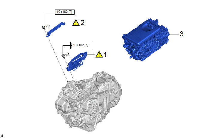
|
Procedure |
Part Name Code |
.png) |
.png) |
.png) |
|
|---|---|---|---|---|---|
|
1 |
MOTOR CABLE |
G1148 |
|
- |
- |
|
2 |
TERMINAL CAP |
82823M |
|
- |
- |
|
3 |
INVERTER WITH CONVERTER ASSEMBLY |
G92A0 |
- |
- |
- |
.png) |
Tightening torque for "Major areas involving basic vehicle performance such as moving/turning/stopping" : N*m (kgf*cm, ft.*lbf) |
.png) |
N*m (kgf*cm, ft.*lbf): Specified torque |
PROCEDURE
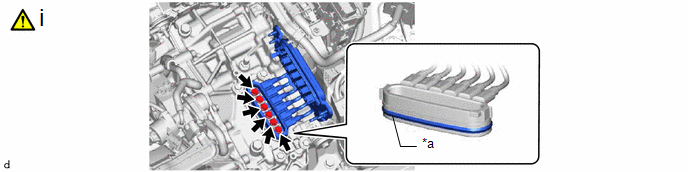
1. INSTALL MOTOR CABLE
|
|
CAUTION: Be sure to wear insulated gloves. NOTICE:
|
|
*a |
Waterproof Seal |
- |
- |
(1) Using an insulated tool, install the motor cable to the hybrid vehicle transaxle assembly with the 6 bolts.
Torque:
10 N·m {102 kgf·cm, 7 ft·lbf}
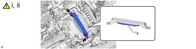
2. INSTALL TERMINAL CAP
|
|
CAUTION: Be sure to wear insulated gloves. NOTICE:
|
|
*a |
Waterproof Seal |
- |
- |
(1) Temporarily install the terminal cap to the hybrid vehicle transaxle assembly with the 2 bolts.
(2) Tighten the 2 bolts to install the terminal cap.
Torque:
10 N·m {102 kgf·cm, 7 ft·lbf}
3. INSTALL INVERTER WITH CONVERTER ASSEMBLY
Click here .gif)


