Toyota Corolla Cross: Inspection
INSPECTION
PROCEDURE
1. INSPECT REAR DOOR COURTESY LIGHT SWITCH ASSEMBLY LH
(a) Check the resistance.
| (1) Measure the resistance according to the value(s) in the table below.
Standard Resistance: |
Tester Connection | Condition |
Specified Condition | |
O31-1 - Switch body |
Not pushed (ON) | Below 1 Ω | |
O31-1 - Switch body |
Pushed (OFF) | 10 kΩ or higher |
If the result is not as specified, replace the rear door courtesy light switch assembly LH. |
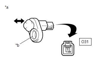 |
|
*a | Component without harness connected
(Rear Door Courtesy Light Switch Assembly LH) | |
*b | Switch Body | | |
2. INSPECT REAR DOOR COURTESY LIGHT SWITCH ASSEMBLY RH
(a) Check the resistance.
| (1) Measure the resistance according to the value(s) in the table below.
Standard Resistance: |
Tester Connection | Condition |
Specified Condition | |
O34-1 - Switch body |
Not pushed (ON) | Below 1 Ω | |
O34-1 - Switch body |
Pushed (OFF) | 10 kΩ or higher |
If the result is not as specified, replace the rear door courtesy light switch assembly RH. |
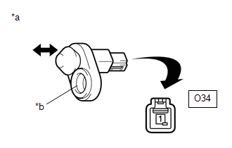 |
|
*a | Component without harness connected
(Rear Door Courtesy Light Switch Assembly RH) | |
*b | Switch Body | | |
READ NEXT:
INSTALLATION CAUTION / NOTICE / HINT COMPONENTS (INSTALLATION)
Procedure Part Name Code
1 REAR DOOR COURTESY LIGHT SWITCH ASSEMBLY
84234
-
RemovalREMOVAL CAUTION / NOTICE / HINT COMPONENTS (REMOVAL)
Procedure Part Name Code
1 NO. 1 ROOM LIGHT ASSEMBLY
81240
- - PROCEDURE
RemovalREMOVAL CAUTION / NOTICE / HINT COMPONENTS (REMOVAL)
Procedure Part Name Code
1 VANITY LIGHT ASSEMBLY
81340
- - CAUTION / NOTICE
SEE MORE:
INSPECTION PROCEDURE 1. INSPECT FUEL PUMP
(a) Measure the resistance according to the value(s) in the table below.
Standard Resistance:
Tester Connection Specified Condition
U - V 0.05 to 3.0 Ω
V - W 0.05 to 3.0 Ω
U - W 0.05 to 3.0 Ω
If th
DESCRIPTION The engine stop and start ECU uses the park/neutral position switch assembly installed to the continuously variable transaxle assembly to detect when the shift lever is in P or N. WIRING DIAGRAM
Refer to DTC P085012. Click here
CAUTION / NOTICE / HINT
NOTICE:
Before replacin



