Toyota Corolla Cross: Inspection
INSPECTION
PROCEDURE
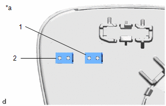
1. INSPECT OUTER MIRROR LH
(a) Check the operation of the mirror heater.
| (1) Measure the resistance according to the value(s) in the table below.
Standard Resistance: |
Tester Connection | Condition |
Specified Condition | |
1 - 2 | 25°C |
3.57 to 4.83 Ω | If the result is not as specified, replace the outer mirror LH. |
 |
|
*a | Component without harness connected
(Outer Mirror LH) | | |
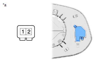
(b) Check the operation of the outer rear view mirror indicator. (w/ Blind Spot Monitor System)
(1) Connect 4 new 1.5 V dry-cell batteries in series.
| (2) Apply 6 V dry-cell batteries to the terminals of the connector, and check the blind spot monitor indicator condition.
NOTICE: Do not apply a voltage of more than 6 V. OK: |
Battery Connection | Specified Condition | |
1 - Positive (+) end of the 6 V dry-cell battery 2 - Negative (-) end of the 6 V dry-cell battery |
Blind spot monitor indicator comes on |
If the result is not as specified, replace the outer mirror LH. |
 |
|
*a | Component without harness connected
(Outer Mirror LH) | | |
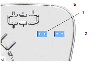
2. INSPECT OUTER MIRROR RH
(a) Check the operation of the mirror heater.
| (1) Measure the resistance according to the value(s) in the table below.
Standard Resistance: |
Tester Connection | Condition |
Specified Condition | |
1 - 2 | 25°C |
3.57 to 4.83 Ω | If the result is not as specified, replace the outer mirror RH. |
 |
|
*a | Component without harness connected
(Outer Mirror RH) | | |
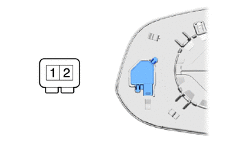
(b) Check the operation of the outer rear view mirror indicator. (w/ Blind Spot Monitor System)
(1) Connect 4 new 1.5 V dry-cell batteries in series.
| (2) Apply 6 V dry-cell batteries to the terminals of the connector, and check the blind spot monitor indicator condition.
NOTICE: Do not apply a voltage of more than 6 V. OK: |
Battery Connection | Specified Condition | |
1 - Positive (+) end of the 6 V dry-cell battery 2 - Negative (-) end of the 6 V dry-cell battery |
Blind spot monitor indicator comes on |
If the result is not as specified, replace the outer mirror RH. |
 |
|
*a | Component without harness connected
(Outer Mirror RH) | | |
READ NEXT:
INSTALLATION CAUTION / NOTICE / HINT COMPONENTS (INSTALLATION)
Procedure Part Name Code
1 OUTER MIRROR
87961
- - CAUTION / NOTICE / HINT
HINT:
PARTS LOCATION ILLUSTRATION
*1 OUTER REAR VIEW MIRROR ASSEMBLY LH
*2 OUTER REAR VIEW MIRROR ASSEMBLY RH
*3 OUTER MIRROR LH
*4 OUTER MIRROR RH
*5 OUTER MIRROR S
SEE MORE:
DESCRIPTION Refer to DTC P003012. Click here
Refer to DTC P003612. Click here
HINT: Although the DTC title says O2 sensor, this DTC relates to the air fuel ratio sensors (sensor 1 and sensor 2).
DTC No. Detection Item
DTC Detection Condition Trouble Area
MIL Note
DISASSEMBLY
CAUTION / NOTICE / HINT
COMPONENTS (DISASSEMBLY)
Procedure
Part Name Code
1
CYLINDER BOOT
-
-
-
2
REAR DISC BRAKE PISTON
-


