Toyota Corolla Cross: Parts Location
Toyota Corolla Cross (2022-2026) Service Manual / Vehicle Exterior / Mirror (ext) / Power Mirror Control System / Parts Location
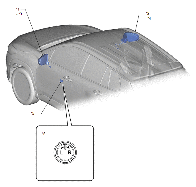
PARTS LOCATION
ILLUSTRATION
|
*1 | OUTER REAR VIEW MIRROR ASSEMBLY LH |
*2 | OUTER REAR VIEW MIRROR ASSEMBLY RH |
|
*3 | OUTER MIRROR LH |
*4 | OUTER MIRROR RH |
|
*5 | OUTER MIRROR SWITCH ASSEMBLY |
*6 | MIRROR SELECT AND SURFACE ADJUST SWITCH |
ILLUSTRATION
|
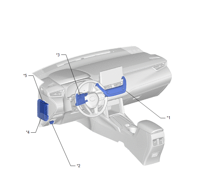
*1 | AIR CONDITIONING CONTROL ASSEMBLY - REAR WINDOW DEFOGGER SWITCH |
*2 | DLC3 |
|
*3 | AIR CONDITIONING AMPLIFIER ASSEMBLY |
*4 | POWER DISTRIBUTION BOX ASSEMBLY - MIR HTR FUSE |
|
*5 | MAIN BODY ECU (MULTIPLEX NETWORK BODY ECU) |
- | - |


