Toyota Corolla Cross: Inspection
INSPECTION
PROCEDURE
1. INSPECT CAM TIMING OIL CONTROL SOLENOID ASSEMBLY
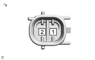
(a) Check the resistance.
| (1) Measure the resistance according to the value(s) in the table below.
Standard Resistance: |
Tester Connection | Condition |
Specified Condition | |
1 - 2 | 0°C (32°F) |
6.3 to 7.3 Ω | |
20°C (68°F) | 6.9 to 7.9 Ω | |
40°C (104°F) | 7.4 to 8.6 Ω |
If the result is not as specified, replace the cam timing oil control solenoid assembly. |
 |
|
*a | Component without harness connected
(Cam Timing Oil Control Solenoid Assembly) | | |
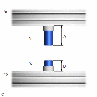
(b) Stroke Amount Inspection
| (1) Using vernier calipers, measure length (A) and (B) with the shaft of the cam timing oil control solenoid assembly set in the respective positions shown in the illustration.
NOTICE: Do not apply auxiliary battery voltage to the terminals of the cam timing oil control solenoid assembly.
HINT: If the shaft does not extend under its own weight, extend the shaft with your fingers. |
 |
|
*a | Shaft Side Facing Down | |
*b | Shaft Side Facing Up | |
*c | Shaft | | |
(2) Calculate the stroke amount based on the difference of length (A) and (B).
Standard:
4.3 mm (0.169 in.) or more
HINT:
Stroke amount = length (A) - length (B)
If the value is not as specified, replace the cam timing oil control solenoid assembly.
READ NEXT:
INSTALLATION CAUTION / NOTICE / HINT COMPONENTS (INSTALLATION)
Procedure Part Name Code
1 O-RING
-
- -
2 CAM TIMING OIL CONTROL
ON-VEHICLE INSPECTION PROCEDURE
1. REMOVE CAM TIMING OIL CONTROL SOLENOID ASSEMBLY Click here
2. INSPECT CAMSHAFT TIMING OIL CONTROL VALVE ASSEMBLY (EXHAUST CAMSHAFT TIMING GEAR BOLT ASSEMBLY)
SEE MORE:
DESCRIPTION If warm air blows from the registers regardless of the temperature setting of the air conditioning system, the following factors may be the cause.
Symptom Factor
No cool air comes out
(Blower control is normal)
Compressor with pulley assembly mal
PROCEDURE
1.
CONFIRM PROBLEM SYMPTOM
(a) Confirm the problem symptom.
Symptom
Proceed to
Noise occurs from V-ribbed belt.
A
Noise occurs from generator assembly.
B
B


