Toyota Corolla Cross: Inspection
INSPECTION
PROCEDURE
1. INSPECT NAVIGATION ANTENNA ASSEMBLY
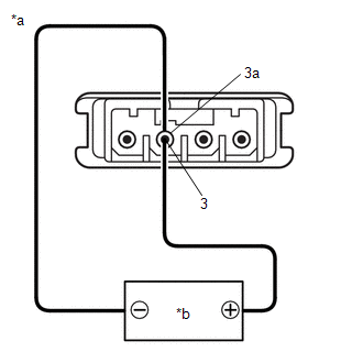
(a) Current consumption check: (GPS)
|
(1) Measure the current consumption according to the value(s)
in the table below.
Standard Current:
|
Tester Connection
|
Condition
|
Specified Condition
|
|
3 (core) - 3a (shield)
|
4.2 to 5 V applied between terminals 3 and 3a
|
10 to 30 mA
|
NOTICE:
Do not apply 6 V or more between terminals 3 and 3a.
HINT:
If a stable power supply is not available, connect 4 nickel-metal
hydride batteries (1.2 V each) or equivalent in series.
If the result is not as specified, replace the navigation
antenna assembly.
|
 |
|
*a
|
Component without harness connected
(Navigation Antenna Assembly)
|
|
*b
|
Voltage Applied between Terminals
|
|
|
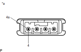
(b) Resistance check: (Telephone Sub)
|
(1) Measure the resistance according to the value(s) in the
table below.
Standard Resistance:
|
Tester Connection
|
Condition
|
Specified Condition
|
|
4 (core) - 4a (shield)
|
Always
|
9.0 to 11 kΩ
|
If the result is not as specified, replace the navigation
antenna assembly.
|
 |
|
*a
|
Component without harness connected
(Navigation Antenna Assembly)
|
|
|
READ NEXT:
INSTALLATION
CAUTION / NOTICE / HINT
COMPONENTS (INSTALLATION)
Procedure
Part Name Code
1
NAVIGATION ANTENNA ASSEMBLY
REMOVAL
CAUTION / NOTICE / HINT
COMPONENTS (REMOVAL)
Procedure
Part Name Code
1
INSTRUMENT PANEL SAFETY PAD ASSEMBLY
SEE MORE:
DESCRIPTION HINT: These DTCs relate to the accelerator pedal position sensor.
Refer to DTC P212012. Click here
DTC No. Detection Item
DTC Detection Condition Trouble Area
MIL Note
P212514 Throttle/Pedal Position Sensor/Switch "E" Circuit Short to Ground or Open
CUSTOMIZE PARAMETERS CUSTOMIZE WIRELESS DOOR LOCK CONTROL SYSTEM
Click here CUSTOMIZE SMART KEY SYSTEM (for Entry Function)
HINT: The following items can be customized.
NOTICE:
When the customer requests a change in a function, first make sure that the function can be customized.
Re


