Toyota Corolla Cross: Brake System Control Module "A" System Voltage Line Internal Electronic Failure (C117A49,C137BA2)
DESCRIPTION
If a malfunction is detected in the power supply circuit, the skid control ECU (brake actuator assembly) stores this DTC and the fail-safe function prohibits ABS operation.
This DTC is stored when the +BS terminal voltage meets one of the DTC detection conditions due to a malfunction in the power supply or charging circuit such as the auxiliary battery or alternator circuit, etc.
The DTC is cleared when the +BS terminal voltage returns to normal.
|
DTC No. |
Detection Item |
DTC Detection Condition |
Trouble Area |
|---|---|---|---|
|
C117A49 |
Brake System Control Module "A" System Voltage Line Internal Electronic Failure |
The vehicle speed is 15 km/h (9 mph) or more and the +BS terminal voltage is 9.6 V or more, the skid control ECU (brake actuator assembly) turns on more than one valve at the same time within a short period of time and the valve relay supply voltage drop exceeds the threshold.* |
|
|
C137BA2 |
Brake System Control Module "A" System Voltage System Voltage Low |
Any of the following is detected:
|
|
*: The skid control ECU (brake actuator assembly) monitors the resistance of the power source line at the +BS terminal. A malfunction is detected when an abnormality occurs in the +BS terminal wire harness or its connection and the skid control ECU (brake actuator assembly) determines that the wiring resistance at the +BS terminal exceeds the standard resistance.
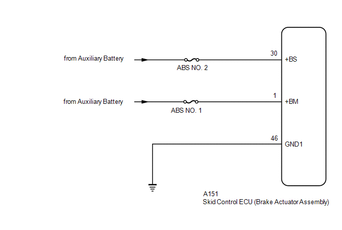
WIRING DIAGRAM
CAUTION / NOTICE / HINT
NOTICE:
- Inspect the fuses for circuits related to this system before performing the following procedure.
- Before performing troubleshooting, make sure to confirm that the auxiliary
battery voltage is normal.
Click here
.gif)
PROCEDURE
|
1. |
CHECK HARNESS AND CONNECTOR (POWER SOURCE TERMINAL) |
|
(a) Make sure that there is no looseness at the locking part and the connecting part of the connector. OK: The connector is securely connected. |
|
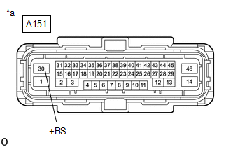
(b) Disconnect the A151 skid control ECU (brake actuator assembly) connector.
(c) Check both the connector case and the terminals for deformation and corrosion.
OK:
No deformation or corrosion.
(d) Measure the voltage according to the value(s) in the table below.
Standard Voltage:
|
Tester Connection |
Condition |
Specified Condition |
|---|---|---|
|
A151-30 (+BS) - Body ground |
Always |
11 to 14 V |
| NG | .gif)
|
REPAIR OR REPLACE HARNESS OR CONNECTOR |
|
.gif)
|
2. |
CHECK HARNESS AND CONNECTOR (POWER SOURCE TERMINAL) |
|
(a) Make sure that there is no looseness at the locking part and the connecting part of the connector. OK: The connector is securely connected. |
|
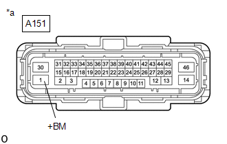
(b) Disconnect the A151 skid control ECU (brake actuator assembly) connector.
(c) Check both the connector case and the terminals for deformation and corrosion.
OK:
No deformation or corrosion.
(d) Measure the voltage according to the value(s) in the table below.
Standard Voltage:
|
Tester Connection |
Condition |
Specified Condition |
|---|---|---|
|
A151-1 (+BM) - Body ground |
Always |
11 to 14 V |
| OK |
|
REPLACE BRAKE ACTUATOR ASSEMBLY |
| NG |
|
REPAIR OR REPLACE HARNESS OR CONNECTOR |


