Toyota Corolla Cross: High Beam Headlight Circuit
DESCRIPTION
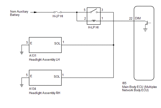
The main body ECU (multiplex network body ECU) controls the high beam headlights.
WIRING DIAGRAM
CAUTION / NOTICE / HINT
NOTICE:
- Before replacing the main body ECU (multiplex network body ECU), refer to refer to Registration.*1
Click here
.gif)
- Check the operation of the low beam headlights. If the low beam headlights do not operate normally, refer to Problem Symptoms Table.
Click here
- First perform the communication function inspections in How to Proceed with Troubleshooting to confirm that there are no CAN communication malfunctions before troubleshooting this symptom.
for HEV Model: Click here
for Gasoline Model: Click here
- *1: w/ Smart Key System
PROCEDURE
|
1. | PERFORM ACTIVE TEST USING GTS |
(a) Enter the following menus: Body Electrical / Main Body / Active Test.
(b) Perform the Active Test according to the display on the GTS.
Body Electrical > Main Body > Active Test|
Tester Display | Measurement Item |
Control Range | Diagnostic Note |
|---|---|---|---|
|
High Beam Headlight | High beam headlights |
OFF or ON | - |
|
Tester Display |
|---|
| High Beam Headlight |
OK:
High beam headlights illuminate.
| OK | .gif) | PROCEED TO NEXT SUSPECTED AREA SHOWN IN PROBLEM SYMPTOMS TABLE |
|
.gif)
| 2. |
INSPECT H-LP HI RELAY |
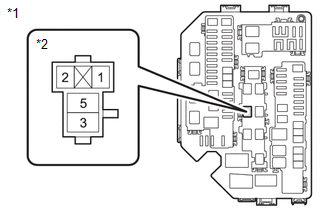
(a) Remove the H-LP HI relay from the No. 1 engine room relay block.
(b) Inspect the H-LP HI relay.
Click here
| NG | |
REPLACE H-LP HI RELAY |
|
| 3. |
CHECK HARNESS AND CONNECTOR (H-LP HI RELAY - BATTERY) |
| (a) Measure the voltage according to the value(s) in the table below. Standard Voltage:
|
|
| NG | | REPAIR OR REPLACE HARNESS OR CONNECTOR |
|
| 4. |
CHECK HARNESS AND CONNECTOR (H-LP HI RELAY - HEADLIGHT ASSEMBLY LH AND HEADLIGHT ASSEMBLY RH AND BODY GROUND) |
(a) Disconnect the A131 headlight assembly LH connector.
(b) Disconnect the A134 headlight assembly RH connector.
(c) Measure the resistance according to the value(s) in the table below.
Standard Resistance:
|
Tester Connection | Condition |
Specified Condition |
|---|---|---|
|
Relay terminal 3 - A131-1 (SOL) |
Always | Below 1 Ω |
|
Relay terminal 3 - A134-1 (SOL) |
Always | Below 1 Ω |
|
A131-5 (E) - Body ground |
Always | Below 1 Ω |
|
A134-5 (E) - Body ground |
Always | Below 1 Ω |
|
Relay terminal 3 - Body ground |
Always | 10 kΩ or higher |
| NG | | REPAIR OR REPLACE HARNESS OR CONNECTOR |
|
| 5. |
CHECK HARNESS AND CONNECTOR (H-LP HI RELAY - MAIN BODY ECU (MULTIPLEX NETWORK BODY ECU)) |
(a) Disconnect the I85 main body ECU (Multiplex network body ECU) connector.
(b) Measure the resistance according to the value(s) in the table below.
Standard Resistance:
|
Tester Connection | Condition |
Specified Condition |
|---|---|---|
|
Relay terminal 1 - I85-22 (DIM) |
Always | Below 1 Ω |
|
Relay terminal 1- Body ground |
Always | 10 kΩ or higher |
| OK | | REPLACE MAIN BODY ECU (MULTIPLEX NETWORK BODY ECU) |
| NG | | REPAIR OR REPLACE HARNESS OR CONNECTOR |


