Toyota Corolla Cross: Vsc Off Switch (for Instrument Panel Side)
Removal
REMOVAL
CAUTION / NOTICE / HINT
COMPONENTS (REMOVAL)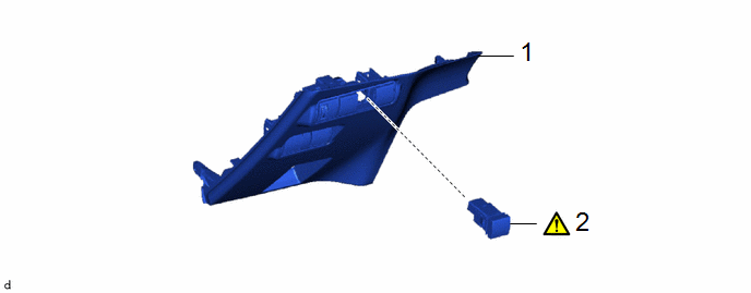
|
Procedure |
Part Name Code |
.png) |
.png) |
.png) |
|
|---|---|---|---|---|---|
|
1 |
LOWER NO. 1 INSTRUMENT PANEL FINISH PANEL |
55432D |
- |
- |
- |
|
2 |
VSC OFF SWITCH |
84988L |
|
- |
- |
PROCEDURE
1. REMOVE LOWER NO. 1 INSTRUMENT PANEL FINISH PANEL
Click here .gif)
2. REMOVE VSC OFF SWITCH
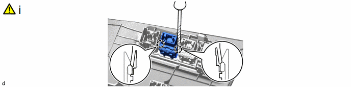
(1) Using a screwdriver with its tip wrapped with protective tape, disengage the claws to remove the auto high beam switch.
Inspection
INSPECTION
PROCEDURE
1. INSPECT VSC OFF SWITCH
|
(a) Make sure that there is no looseness in the locking part and the connecting part of the connector. OK: The connector is securely connected. |
|
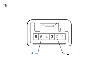
(b) Disconnect the VSC OFF switch connector.
(c) Check both the connector case and the terminals for deformation and corrosion.
OK:
No deformation or corrosion.
(d) Measure the resistance according to the value(s) in the table below.
Standard Resistance:
|
Tester Connection |
Condition |
Specified Condition |
|---|---|---|
|
5 (+) - 2 (E) |
Switch pushed |
Below 1 Ω |
|
5 (+) - 2 (E) |
Switch not pushed |
10 kΩ or higher |
HINT:
If the result is not as specified, replace the VSC OFF switch.
Installation
INSTALLATION
CAUTION / NOTICE / HINT
COMPONENTS (INSTALLATION)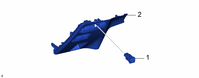
|
Procedure |
Part Name Code |
.png) |
.png) |
.png) |
|
|---|---|---|---|---|---|
|
1 |
VSC OFF SWITCH |
84988L |
- |
- |
- |
|
2 |
LOWER NO. 1 INSTRUMENT PANEL FINISH PANEL |
55432D |
- |
- |
- |
PROCEDURE
1. INSTALL VSC OFF SWITCH
2. INSTALL LOWER NO. 1 INSTRUMENT PANEL FINISH PANEL
Click here .gif)


