Toyota Corolla Cross: Terminals Of Ecu
TERMINALS OF ECU
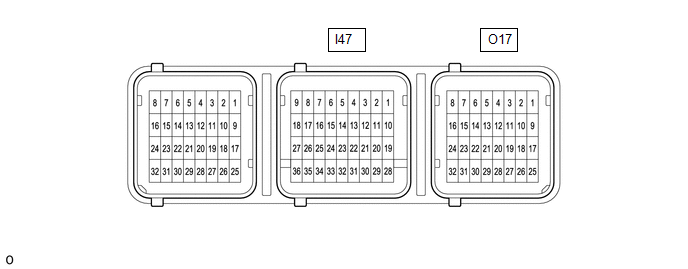
AIRBAG ECU ASSEMBLY
|
Terminal No. | Terminal Symbol |
Destination |
| I47-26 |
CANH | CAN communication line |
|
I47-27 | CANL |
CAN communication line |
|
I47-32 | E2 |
Ground |
| I47-33 |
E1 | Ground |
|
I47-34 | P-AB |
Passenger airbag OFF indicator (Map light assembly) |
|
I47-35 | PAON |
Passenger airbag ON indicator (Map light assembly) |
|
I47-36 | IGR |
A/BAG-IGR fuse |
|
O17-18 | GNDR |
Passenger seat buckle switch (Front seat inner belt assembly RH) |
|
O17-24 | SVC |
- Front occupant classification sensor LH (Front Seat Cushion Spring Sub-assembly RH)
- Rear occupant classification sensor LH (Front Seat Cushion Spring Sub-assembly RH)
|
| O17-27 |
RBE+ | Passenger seat buckle switch (Front seat inner belt assembly RH) |
|
O17-31 | SGD |
- Front occupant classification sensor LH (Front Seat Cushion Spring Sub-assembly RH)
- Rear occupant classification sensor LH (Front Seat Cushion Spring Sub-assembly RH)
|
| O17-32 |
SIG |
- Front occupant classification sensor LH (Front Seat Cushion Spring Sub-assembly RH)
- Rear occupant classification sensor LH (Front Seat Cushion Spring Sub-assembly RH)
|
READ NEXT:
DTC CHECK / CLEAR DTC CHECK (a) Check for DTCs (Test Failed / Pending / Confirmed). Body Electrical > SRS Airbag > Trouble Codes
GTS Display Description
Test Failed Shows the m
FREEZE FRAME DATA DESCRIPTION (a) When an occupant classification system DTC is stored, the airbag ECU assembly stores the current vehicle (ECU or sensor) state as Freeze Frame Data.
CHECK FREEZE FR
FAIL-SAFE CHART FAIL-SAFE FUNCTION (a) The following chart shows the status of the front passenger SRS items and passenger airbag ON/OFF indicator operation under failure condition.
Passenger Ai
SEE MORE:
INSPECTION PROCEDURE 1. INSPECT CAM TIMING OIL CONTROL SOLENOID ASSEMBLY
(a) Check the resistance.
(1) Measure the resistance according to the value(s) in the table below.
Standard Resistance:
Tester Connection Condition
Specified Condition
1 - 2 0 °C (32 °F)
INSPECTION PROCEDURE 1. INSPECT REAR HEIGHT CONTROL SENSOR SUB-ASSEMBLY LH (for 2WD)
(a) Preparation for check. (1) Confirm the standard, high and low positions of the link that will be used in the following inspection.
The standard position is 53° from the maximum link angle (high) and 113° f


