Toyota Corolla Cross Owners & Service Manuals

Toyota Corolla Cross: Terminals Of Ecu

TERMINALS OF ECU

CHECK POWER STEERING ECU ASSEMBLY
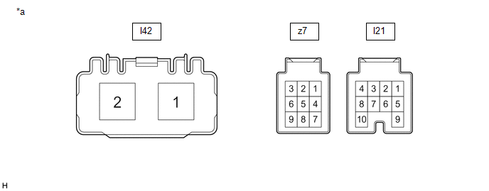
*a

Component without harness connected

(Power Steering ECU Assembly)

-

-

(a) Measure the voltage and resistance according to the value(s) in the table below.

NOTICE:

When the EPS warning light is illuminated due to a malfunction, the fail-safe function may cause the voltage of the power steering ECU assembly terminals to become 0 V.

Terminal No. (Symbol)

Terminal Description

Condition

Specified Condition

I21-1 (IG) - Body ground

IG power source

Ignition switch ON

8 to 16 V

I21-7 (CANH) - I21-8 (CANL)

CAN communication line

Ignition switch off

54 to 69 Ω

z7-1 (TRQ2) - z7-2 (TRQG2)

Torque sensor 2 signal

  • Ignition switch ON and steering wheel not being turned (without load)*1
  • Engine running and steering wheel not being turned (without load)*2

2.3 to 2.7 V

  • Ignition switch ON and steering wheel being turned to the right with vehicle stopped*1
  • Engine running and steering wheel being turned to the right with vehicle stopped*2

1.2 to 2.5 V

  • Ignition switch ON and steering wheel being turned to the left with vehicle stopped*1
  • Engine running and steering wheel being turned to the left with vehicle stopped*2

2.5 to 3.8 V

z7-2 (TRQG2) - Body ground

Torque sensor 2 ground

Always

Below 1 Ω

z7-3 (TRQV2) - z7-2 (TRQG2)

Torque sensor 2 voltage source

Ignition switch ON

4.5 to 5.5 V

z7-7 (TRQV1) - z7-8 (TRQG1)

Torque sensor 1 voltage source

Ignition switch ON

4.5 to 5.5 V

z7-8 (TRQG1) - Body ground

Torque sensor 1 ground

Always

Below 1 Ω

z7-9 (TRQ1) - z7-8 (TRQG1)

Torque sensor signal

  • Ignition switch ON and steering wheel not being turned (without load)*1
  • Engine running and steering wheel not being turned (without load)*2

2.3 to 2.7 V

  • Ignition switch ON and steering wheel being turned to the right with vehicle stopped*1
  • Engine running and steering wheel being turned to the right with vehicle stopped*2

2.5 to 3.8 V

  • Ignition switch ON and steering wheel being turned to the left with vehicle stopped*1
  • Engine running and steering wheel being turned to the left with vehicle stopped*2

1.2 to 2.5 V

I42-1 (PIG) - Body ground

Power source

Always

9 to 16 V

I42-2 (PGND) - Body ground

Power ground

Always

Below 1 Ω

  • *1: for HEV Model
  • *2: for Gasoline Model

If the result is not as specified, the ECU may be malfunctioning.

    READ NEXT:

     Diagnosis System

    DIAGNOSIS SYSTEM DTC The rack and pinion power steering gear assembly stores a DTC when it detects a malfunction in the ECU and power steering system circuit. CHECK DLC3 (a) Check the DLC

     Freeze Frame Data

    FREEZE FRAME DATA FREEZE FRAME DATA NOTICE: It is difficult to show the specified values (judgment values) clearly because freeze frame data values change significantly due to differences in

     Fail-safe Chart

    FAIL-SAFE CHART If a problem occurs in the power steering system, the power steering assist will be stopped or the amount of power assist will be decreased to protect the system. Power Steering Sy

    SEE MORE:

     Generator Phase U Current Sensor Circuit Short to Battery (P0E0012,P0E0014,P0E001F,P0E0412,P0E0414,P0E041F,P0E0812,P0E0814,P0E081F)

    DTC SUMMARY MALFUNCTION DESCRIPTION These DTCs indicate that the current sensor value is abnormal. The cause of this malfunction may be one of the following: Internal inverter malfunction Inverter with converter assembly internal circuit malfunction Inverter low-voltage circuit malfunctio

     Removal

    REMOVAL CAUTION / NOTICE / HINT COMPONENTS (REMOVAL) Procedure Part Name Code 1 TIMING CHAIN COVER ASSEMBLY 11310 - - - 2 OIL PAN SUB-ASSEMBLY 12101 - - 3 OIL STRAINER SUB-ASSEMBLY 15104

    © 2020-2026 Copyright www.tcorollacross.com PT NL