Toyota Corolla Cross: System Diagram
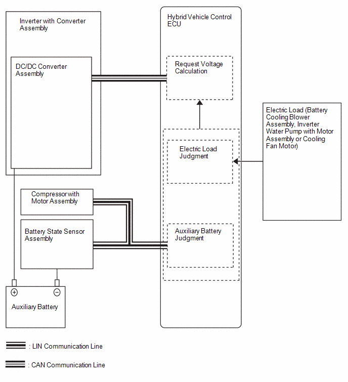
SYSTEM DIAGRAM
READ NEXT:
PROCEDURE
1.
VEHICLE BROUGHT TO WORKSHOP
NEXT
2.
CONFIRM PROBLEM SYMPTOMS
TERMINALS OF ECU
*a
Hybrid Vehicle Control ECU
-
-
HINT:
The standard normal voltage between each pair of hybrid vehicle control ECU terminals
DIAGNOSIS SYSTEM
DLC3 (Data Link Connector 3)
(a) Check the DLC3.
Click here
AUXILIARY BATTERY VOLTAGE
Standard Voltage:
Switch Condition
Specified Condition
SEE MORE:
Adjustment procedure
1. Hold the steering wheel and
push the lever down.
2. Adjust to the ideal position by
moving the steering wheel
horizontally and vertically.
After adjustment, pull the lever up
to secure the steering wheel.
WARNING
■Caution while driving
Do not adjust the steering wheel
wh
DESCRIPTION
When the system is starting up and the skid control ECU (brake
actuator assembly) detects a speed sensor circuit malfunction via the speed sensor
circuit self-diagnosis function, this DTC is stored.
DTC No.
Detection Item
DTC Detection Condition
 How To Proceed With Troubleshooting
 Steering wheel
