Toyota Corolla Cross: System Diagram
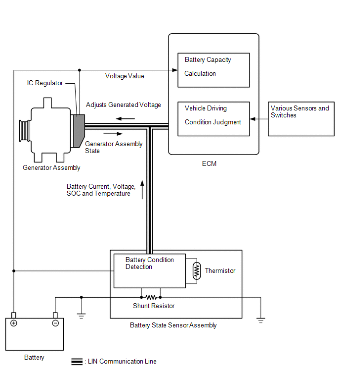
SYSTEM DIAGRAM
READ NEXT:
CAUTION / NOTICE / HINT
HINT:
*: Use the GTS.
PROCEDURE
1.
VEHICLE BROUGHT TO WORKSHOP
NEXT
PROBLEM SYMPTOMS TABLE
HINT:
Use the table below to help determine the cause of problem symptoms. If
multiple suspected areas are listed, the potential causes of the symptoms are
listed in
TERMINALS OF ECM
HINT:
The standard normal voltage and resistance between each pair of ECM terminals
is shown in the table below. The appropriate conditions for checking each pair of
terminals
SEE MORE:
DESCRIPTION The headlight ECU sub-assembly LH and headlight ECU sub-assembly RH internally boost the power supply voltage to ensure a constant supplied current for the Lo/Hi beam LED of their respective headlight.
By monitoring the LED power supply voltage, abnormal current and malfunctions can be
DESCRIPTION The flow shutting valve (for heater control) used for the variable cooling system is a magnet type valve that is closed when the engine is warming up to prevent coolant from flowing through the heater passage which reduces engine warm up time.
DTC No. Detection Item
DTC Dete
 How To Proceed With Troubleshooting
 Headlight Source LH Malfunction (B243900,B243A00)
