Toyota Corolla Cross: Terminals Of Ecm
TERMINALS OF ECM
HINT:
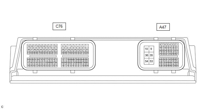
The standard normal voltage and resistance between each pair of ECM terminals
is shown in the table below. The appropriate conditions for checking each pair of
terminals are also indicated. The result of checks should be compared with the standard
normal voltage and resistance for that pair of terminals, displayed in the Specified
Condition column. The illustration above can be used as a reference to identify
the ECM terminal locations.
Terminal No. (Symbol)
|
Terminal Description
|
Condition
|
Specified Condition
|
A47-10 (E1) - Body ground
|
Ground
|
Always
|
Below 1 Ω
|
A47-1 (BATT) - A47-10 (E1)
|
Battery
(for measuring battery voltage and for ECM memory)
|
Always
|
11 to 14 V
|
C76-62 (LIN) - Body ground
|
LIN communication line
|
Ignition switch off
(while LIN communication stopped)
|
10 kΩ or higher
|
READ NEXT:
DIAGNOSIS SYSTEM
DLC3 (Data Link Connector 3)
(a) Check the DLC3.
Click here
BATTERY VOLTAGE
Standard Voltage:
11 to 14 V
If the voltage is below 11 V, replace or recharge the battery.
FREEZE FRAME DATA
FREEZE FRAME DATA
(a) Enter the following menus.
Powertrain > Engine > Trouble Codes
(b) Select a DTC in order to display its freeze frame data.
(c) Check the freeze frame
FAIL-SAFE CHART
If the following DTC is stored, the ECM enters fail-safe mode to allow the vehicle
to be driven temporarily.
Charging System
DTC No.
Fail-safe Operation
SEE MORE:
DTC SUMMARY MALFUNCTION DESCRIPTION These DTCs indicate that the current sensor value is abnormal. The cause of this malfunction may be one of the following: Internal inverter malfunction
Current sensor malfunction
Inverter with converter assembly internal circuit malfunction
DESCRI
DESCRIPTION
The airbag ECU assembly has a built-in yaw rate and acceleration
sensor and detects the vehicle condition.
The skid control ECU (brake actuator assembly) memorizes the
range of the acceleration sensor (airbag ECU assembly) and the range of vehicle
speed calculated using each spee