Toyota Corolla Cross: System Diagram
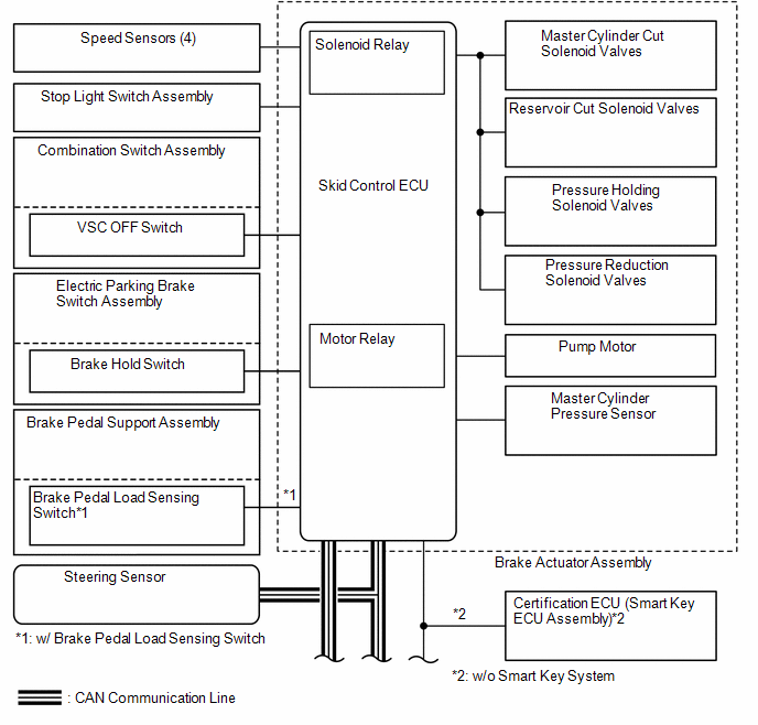
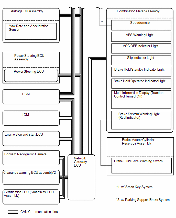
SYSTEM DIAGRAM
READ NEXT:
CAUTION / NOTICE / HINT
HINT:
*: Use the GTS.
PROCEDURE
1.
VEHICLE BROUGHT TO WORKSHOP
NEXT
TEST MODE PROCEDURE
SENSOR CHECK USING DEALER MODE (SIGNAL CHECK)
NOTICE:
After replacing or removing and installing a speed sensor, perform Dealer
Mode (Signal Check) inspection to confirm
UTILITY
DESCRIPTION
(a) Refer to the table below and then perform the necessary operation
according to the part to be replaced in order to perform calibration.
Parts to be Replaced / O
SEE MORE:
INSTALLATION CAUTION / NOTICE / HINT
Procedure Part Name Code
1 NO. 2 EXHAUST MANIFOLD HEAT INSULATOR
17168 -
- -
2 EXHAUST MANIFOLD (TWC: Front Catalyst)
17141
- -
3 MANIFOLD STAY
17118 -
DIAGNOSIS SYSTEM
DESCRIPTION
(a) Blind spot monitor data and Diagnostic Trouble Codes (DTCs)
can be read from the Data Link Connector 3 (DLC3) of the vehicle. When the system
seems to be malfunctioning, use the GTS to check for malfunctions and to perform
repairs.
CHECK DLC3
(a) Check the
 How To Proceed With Troubleshooting
 Installation
