Toyota Corolla Cross: System Diagram
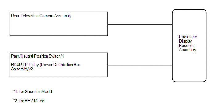
SYSTEM DIAGRAM
READ NEXT:
CAUTION / NOTICE / HINT
HINT:
Use the following procedure to troubleshoot the rear view monitor system.
*: Use the GTS.
PROCEDURE
1.
VEHICLE BROUGHT TO WORKSHOP
PROBLEM SYMPTOMS TABLE
HINT:
Use the table below to help determine the cause of problem symptoms.
If multiple suspected areas are listed, the potential causes of the symptoms
are listed i
TERMINALS OF ECU
CHECK RADIO AND DISPLAY RECEIVER ASSEMBLY
(a) Disconnect the I55 and I253 radio and display receiver assembly
connectors.
(b) Measure the voltage and resistance according to th
SEE MORE:
DESCRIPTION When the drive mode select switch (combination switch assembly) is operated, a switch signal is sent to the hybrid vehicle control ECU and the hybrid vehicle control ECU changes the drive mode. WIRING DIAGRAM
PROCEDURE
1. READ VALUE USING GTS (CAN BUS CHECK)
Cl
DTC SUMMARY MALFUNCTION DESCRIPTION The hybrid vehicle control ECU detects a VL sensor malfunction.
The cause of this malfunction may be one of the following: Inverter voltage (VL) sensor internal circuit malfunction
Voltage sensor malfunction
Motor generator control ECU (MG ECU) malf
 How To Proceed With Troubleshooting
 Drive Mode Select Switch Circuit
