Toyota Corolla Cross: Telephone Main Antenna Circuit Short to Ground (B15CB11,B15CB13)
DESCRIPTION
If an open or short circuit in the roof antenna assembly is detected as a result of a terminal check performed by the DCM (telematics transceiver), these DTCs will be stored.
|
DTC No. |
Detection Item |
DTC Detection Condition |
Trouble Area |
|---|---|---|---|
|
B15CB11 |
Telephone Main Antenna Circuit Short to Ground |
Roof antenna assembly impedance (Ω) is lower than the malfunction threshold for 10 seconds or more when the ignition switch is ON (Short circuit) |
|
|
B15CB13 |
Telephone Main Antenna Circuit Open |
Roof antenna assembly impedance (Ω) is higher than the malfunction threshold for 10 seconds or more when the ignition switch is ON (Open circuit) |
|
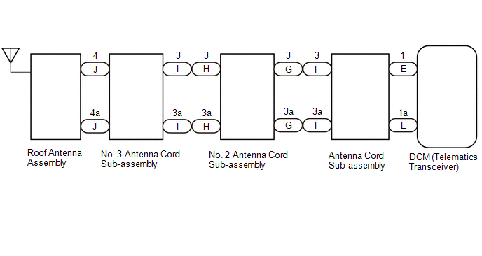
WIRING DIAGRAM
CAUTION / NOTICE / HINT
NOTICE:
- Depending on the parts that are replaced during vehicle inspection or
maintenance, performing initialization, registration or calibration may
be needed. Refer to Precaution for Telematics System.
Click here
.gif)
- When replacing the DCM (telematics transceiver), make sure to replace it with a new one.
PROCEDURE
|
1. |
CLEAR DTC |
(a) Clear the DTCs.
Body Electrical > Telematics > Clear DTCs
|
.gif)
|
2. |
CHECK DTC |
(a) Turn the ignition switch to ON and wait for 10 seconds or more.
(b) Check for DTCs and check that no DTCs are output.
Body Electrical > Telematics > Trouble Codes|
Result |
Proceed to |
|---|---|
|
DTCs are not output |
A |
|
DTC B15CB11 or B15CB13 is output |
B |
| A | .gif)
|
USE SIMULATION METHOD TO CHECK |
|
|
3. |
INSPECT ROOF ANTENNA ASSEMBLY |
|
(a) Remove the roof antenna assembly. HINT: Click here |
|
(b) Measure the resistance according to the value(s) in the table below.
Standard Resistance:
|
Tester Connection |
Condition |
Specified Condition |
|---|---|---|
|
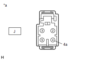
J-4 - J-4a |
Always |
9 to 11 kΩ |
| NG |
|
REPLACE ROOF ANTENNA ASSEMBLY |
|
|
4. |
CHECK NO. 3 ANTENNA CORD SUB-ASSEMBLY |
|
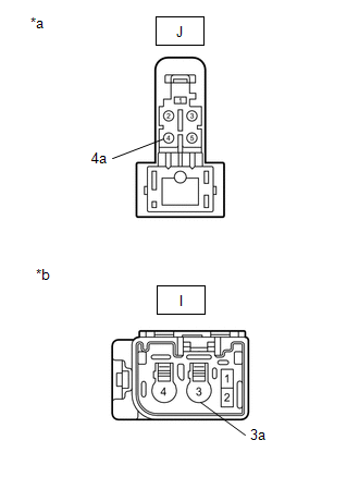
(a) Disconnect the No. 3 antenna cord sub-assembly from the roof antenna assembly connector. |
|
(b) Disconnect the No. 3 antenna cord sub-assembly from the No. 2 antenna cord sub-assembly connector.
(c) Measure the resistance according to the value(s) in the table below.
Standard Resistance:
|
Tester Connection |
Condition |
Specified Condition |
|---|---|---|
|
J-4 - I-3 |
Always |
Below 1 Ω |
|
J-4a - I-3a |
Always |
Below 1 Ω |
|
J-4 - I-3 - Body ground |
Always |
10 kΩ or higher |
| NG |
|
REPLACE NO. 3 ANTENNA CORD SUB-ASSEMBLY |
|
|
5. |
CHECK NO. 2 ANTENNA CORD SUB-ASSEMBLY |
|
(a) Disconnect the No. 2 antenna cord sub-assembly from the No. 3 antenna cord sub-assembly connector. |
|
(b) Disconnect the No. 2 antenna cord sub-assembly from the antenna cord sub-assembly connector.
(c) Measure the resistance according to the value(s) in the table below.
Standard Resistance:
|
Tester Connection |
Condition |
Specified Condition |
|---|---|---|
|
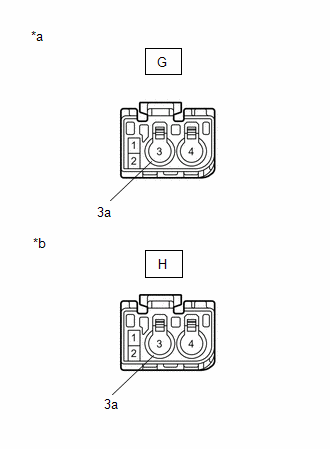
H-3 - G-3 |
Always |
Below 1 Ω |
|
H-3a - G-3a |
Always |
Below 1 Ω |
|
H-3 - G-3 - Body ground |
Always |
10 kΩ or higher |
| NG |
|
REPLACE NO. 2 ANTENNA CORD SUB-ASSEMBLY |
|
|
6. |
INSPECT ANTENNA CORD SUB-ASSEMBLY |
|
(a) Disconnect the antenna cord sub-assembly connector from the No. 2 antenna cord sub-assembly. |
|
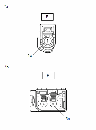
(b) Disconnect the antenna cord sub-assembly connector from the DCM (telematics transceiver).
(c) Measure the resistance according to the value(s) in the table below.
Standard Resistance:
|
Tester Connection |
Condition |
Specified Condition |
|---|---|---|
|
E-1 - F-3 |
Always |
Below 1 Ω |
|
E-1a - F-3a |
Always |
Below 1 Ω |
|
E-1 or F-3 - Body ground |
Always |
10 kΩ or higher |
| NG |
|
REPLACE ANTENNA CORD SUB-ASSEMBLY |
|
|
7. |
REPLACE DCM (TELEMATICS TRANSCEIVER) |
(a) Replace the DCM (telematics transceiver) assembly with a new one.
HINT:
Click here
| NEXT |
|
PERFORM DCM ACTIVATION |


