Toyota Corolla Cross: System Diagram
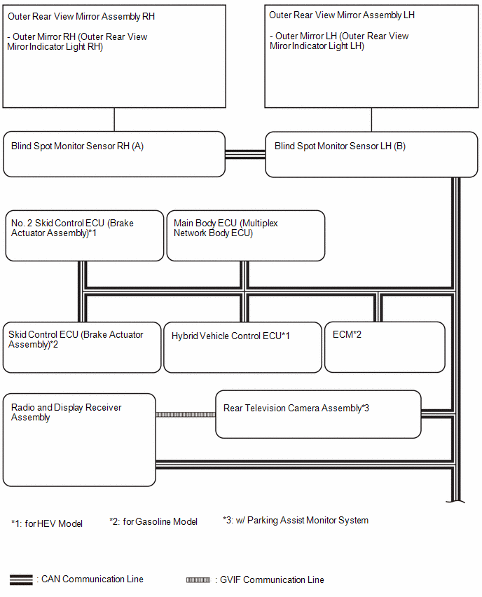
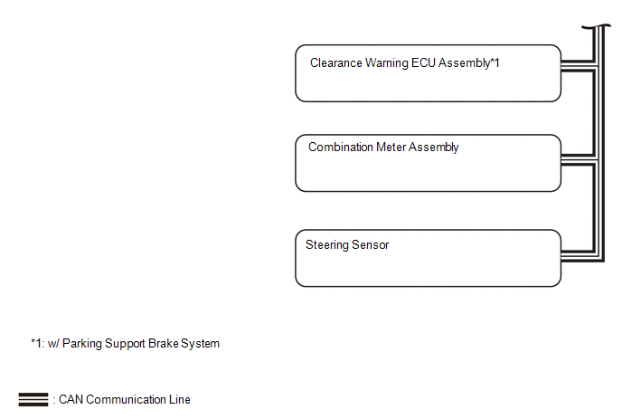
SYSTEM DIAGRAM
READ NEXT:
SYSTEM DESCRIPTION
OPERATION OF OUTER REAR VIEW MIRROR INDICATOR AND RCTA BUZZER (BLIND
SPOT MONITOR BUZZER)
(a) Initial check
(1) When the blind spot monitor system is turned on with the ignitio
CAUTION / NOTICE / HINT
HINT:
Use the following procedure to troubleshoot the blind spot monitor system.
*: Use the GTS.
PROCEDURE
1.
VEHICLE BROUGHT TO WORKSHOP
CUSTOMIZE PARAMETERS
CUSTOMIZE BLIND SPOT MONITOR SYSTEM
(a) Customizing with the GTS
NOTICE:
When the customer requests a change in a function, first make sure that
the function can be cus
SEE MORE:
DESCRIPTION If the air outlet mode does not change even though the air outlet display changes, the following factors may be the cause.
Symptom Factor
Air outlet mode cannot be changed
(Air outlet display changes)
No. 1 air conditioning radiator damper servo
CUSTOMIZE PARAMETERS CUSTOMIZE WIRELESS DOOR LOCK CONTROL SYSTEM
NOTICE:
When the customer requests a change in a function, first make sure that the function can be customized.
Be sure to make a note of the current settings before customizing.
When troubleshooting a function, first ma
 System Description
 Air Vent cannot be Switched
