Toyota Corolla Cross: System Diagram
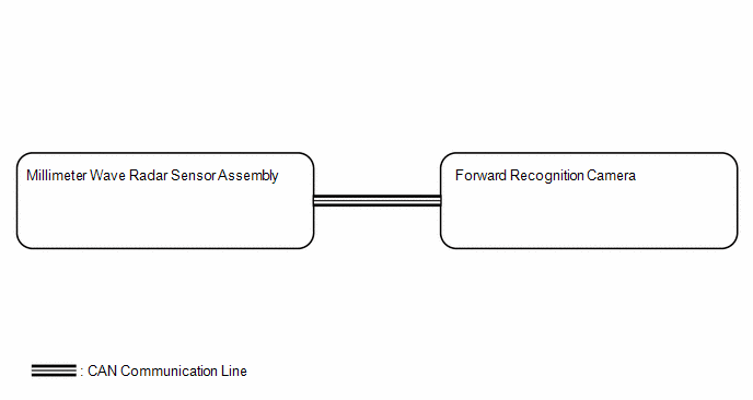
SYSTEM DIAGRAM
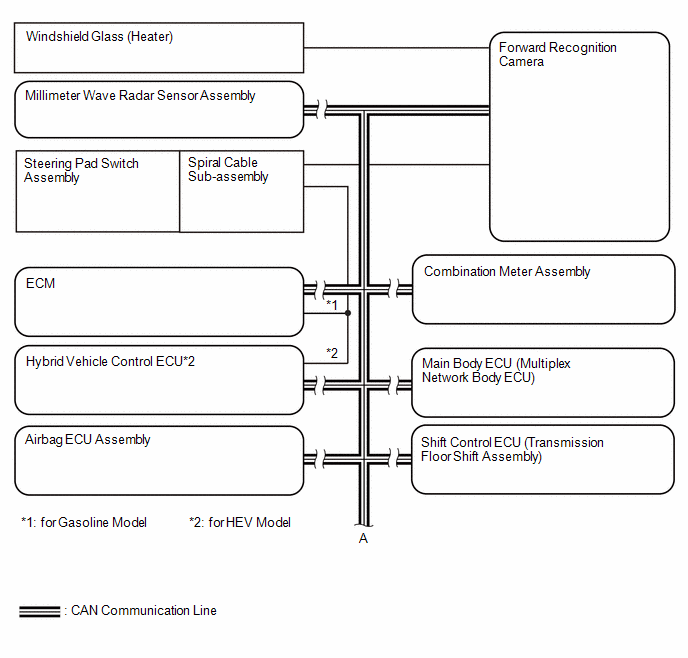
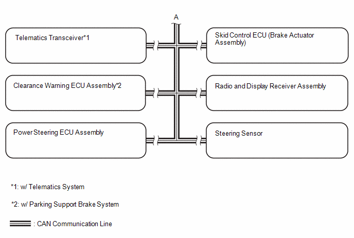
Local BUS Circuit
READ NEXT:
CAUTION / NOTICE / HINT
HINT:
Use the following procedure to troubleshoot the front camera system.
*: Use the GTS.
PROCEDURE
1.
VEHICLE BROUGHT TO WORKSHOP
OPERATION CHECK
*a
Automatic High Beam Indicator Light on Combination Meter
Assembly
AUTOMATIC HIGH BEAM OPERATION CHECK
(a) When all of the following condition
CUSTOMIZE PARAMETERS
CUSTOMIZE FRONT CAMERA SYSTEM
NOTICE:
When the customer requests a change in a function, first make sure that
the function can be customized.
Be sure to make a note o
SEE MORE:
DESCRIPTION The VVT-iE system adjusts the intake valve timing using a motor. Compared to conventional hydraulic VVT systems, the valve timing can be adjusted within a wider range and can be retarded more when starting the engine. As the VVT-iE system can operate at low engine speeds and when the eng
INSTALLATION CAUTION / NOTICE / HINT COMPONENTS (INSTALLATION)
Procedure Part Name Code
1 CAM TIMING CONTROL MOTOR O-RING
13090E
- -
2 CAM TIMING CONTROL MOTOR WITH EDU ASSEMBLY
13090D
- -
N
 How To Proceed With Troubleshooting
 Camshaft Position "A" Actuator Bank 1 General Electrical Failure (P001001)
