Toyota Corolla Cross: Steering Angle Sensor Supply Voltage Circuit Circuit Short to Ground or Open (C14FE14)
DESCRIPTION
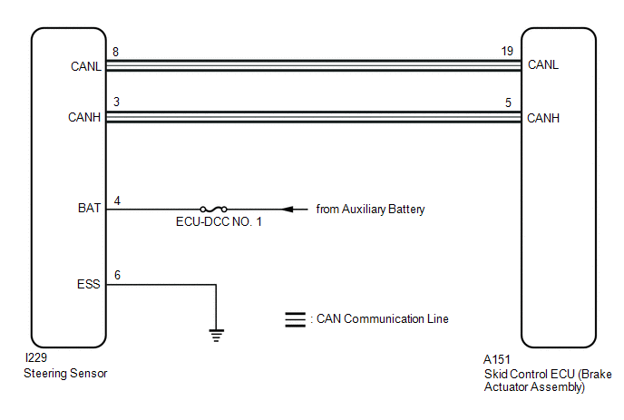
This DTC is stored when the skid control ECU (brake actuator assembly) receives a steering sensor power supply circuit malfunction signal from the steering sensor.
|
DTC No. |
Detection Item |
DTC Detection Condition |
Trouble Area |
MIL |
DTC Output from |
Note |
|---|---|---|---|---|---|---|
|
C14FE14 |
Steering Angle Sensor Supply Voltage Circuit Circuit Short to Ground or Open |
With the +BS terminal voltage between 9.6 and 16.5 V, a steering sensor power supply circuit malfunction signal is received from the steering sensor. |
|
Does not come on |
Brake/EPB |
Output ECU: Skid control ECU (brake actuator assembly) |
WIRING DIAGRAM
CAUTION / NOTICE / HINT
NOTICE:
Inspect the fuses for circuits related to this system before performing the following procedure.
PROCEDURE
|
1. |
CLEAR DTC |
(a) Clear the DTCs.
Chassis > Brake/EPB > Clear DTCs(b) Turn the ignition switch off.
|
.gif)
|
2. |
RECONFIRM DTC |
(a) Based on the Freeze Frame Data and interview with the customer, attempt to reproduce the conditions when the malfunction occurred.
(b) Check if the same DTC is output.
Chassis > Brake/EPB > Trouble Codes|
Result |
Proceed to |
|---|---|
|
C14FE14 is not output |
A |
|
C14FE14 is output |
B |
| A | .gif)
|
USE SIMULATION METHOD TO CHECK |
|
|
3. |
CHECK HARNESS AND CONNECTOR (POWER SOURCE TERMINAL) |
|
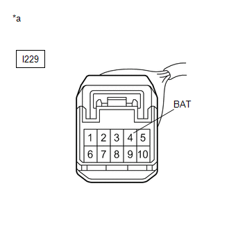
*a |
Front view of wire harness connector (to Steering Sensor) |
(a) Remove the steering wheel and column cover.
(b) Make sure that there is no looseness at the locking part and the connecting part of the connector.
OK:
The connector is securely connected.
(c) Disconnect the I229 steering sensor connector.
(d) Check both the connector case and the terminals for deformation and corrosion.
OK:
No deformation or corrosion.
(e) Measure the voltage according to the value(s) in the table below.
Standard Voltage:
|
Tester Connection |
Condition |
Specified Condition |
|---|---|---|
|
I229-4 (BAT) - Body ground |
Always |
11 to 14 V |
| OK |
|
REPLACE STEERING SENSOR |
| NG |
|
REPAIR OR REPLACE HARNESS OR CONNECTOR |


