Toyota Corolla Cross: Right Rear Wheel Speed Sensor Supply Voltage Circuit Short to Ground or Open (C14E914)
DESCRIPTION
Refer to DTC C051212
Click here .gif)
|
DTC No. |
Detection Item |
DTC Detection Condition |
Trouble Area |
MIL |
DTC Output from |
Note |
|---|---|---|---|---|---|---|
|
C14E914 |
Right Rear Wheel Speed Sensor Supply Voltage Circuit Short to Ground or Open |
An open or short in the speed sensor power supply circuit is detected for 0.12 seconds or more. |
|
Comes on |
Brake/EPB |
|
MONITOR DESCRIPTION
The skid control ECU (brake actuator assembly) has a speed sensor circuit self-diagnosis function.
When the self-diagnosis function that is performed during startup detects that the current of the speed sensor supply power line is within a certain range, the skid control ECU (brake actuator assembly) illuminates the MIL and stores this DTC.
MONITOR STRATEGY
|
Related DTCs |
C14EA: Wheel speed sensor line monitoring for RR (supply line short to GND) |
|
Required Sensors/Components(Main) |
Skid control ECU (brake actuator assembly) |
|
Required Sensors/Components(Related) |
Skid control ECU (brake actuator assembly) |
|
Frequency of Operation |
During initial checking |
|
Duration |
0.12 seconds |
|
MIL Operation |
Immediately |
|
Sequence of Operation |
None |
TYPICAL ENABLING CONDITIONS
|
Monitor runs whenever the following DTCs are not stored |
TMC's intellectual property |
|
Other conditions belong to TMC's intellectual property |
- |
TYPICAL MALFUNCTION THRESHOLDS
|
TMC's intellectual property |
- |
COMPONENT OPERATING RANGE
|
TMC's intellectual property |
- |
CONFIRMATION DRIVING PATTERN
NOTICE:
When performing the normal judgment procedure, make sure that the driver door is closed and is not opened at any time during the procedure.
HINT:
- After repair has been completed, clear the DTC and then check that the vehicle has returned to normal by performing the following All Readiness check procedure.
- When clearing the permanent DTCs, refer to the "CLEAR PERMANENT DTC" procedure.
- Connect the GTS to the DLC3.
- Turn the ignition switch to ON and turn the GTS on.
- Clear the DTCs (even if no DTCs are stored, perform the clear DTC procedure).
- Turn the ignition switch off.
- Turn the ignition switch to ON (READY) and turn the GTS on.
- Wait for 1 second or more. [*]
HINT:
[*]: Normal judgment procedure.
The normal judgment procedure is used to complete DTC judgment and also used when clearing permanent DTCs.
- Enter the following menus: Chassis / Brake/EPB* / Utility / All Readiness.
*: Electric Parking Brake System
- Check the DTC judgment result.
HINT:
- If the judgment result shows NORMAL, the system is normal.
- If the judgment result shows ABNORMAL, the system has a malfunction.
- If the judgment result shows INCOMPLETE, perform driving pattern again.
WIRING DIAGRAM
Refer to DTC C051212.
Click here
PROCEDURE
|
1. |
CHECK HARNESS AND CONNECTOR (SENSOR POWER SOURCE CIRCUIT) |
|
(a) Make sure that there is no looseness at the locking part and the connecting part of the connectors. OK: The connector is securely connected. |
|
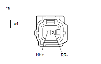
(b) Disconnect the o4 rear speed sensor RH connector.
(c) Check both the connector case and the terminals for deformation and corrosion.
OK:
No deformation or corrosion.
(d) Turn the ignition switch to ON.
(e) Measure the voltage according to the value(s) in the table below.
Standard Voltage:
|
Tester Connection |
Condition |
Specified Condition |
|---|---|---|
|
o4-1 (RR+) - o4-2 (RR-) |
Ignition switch ON |
11 to 14 V |
| OK | .gif)
|
REPLACE REAR SPEED SENSOR RH |
|
.gif)
|
2. |
CHECK HARNESS AND CONNECTOR (SENSOR POWER SOURCE CIRCUIT) |
.png)
|
*a |
Front view of wire harness connector (to Skid Control Sensor Wire RH (No. 1 Parking Brake Wire Assembly)) |
(a) Make sure that there is no looseness at the locking part and the connecting part of the connectors.
OK:
The connector is securely connected.
(b) Disconnect the oO2 skid control sensor wire RH (No. 1 parking brake wire assembly) connector.
(c) Check both the connector case and the terminals for deformation and corrosion.
OK:
No deformation or corrosion.
(d) Turn the ignition switch to ON.
(e) Measure the voltage according to the value(s) in the table below.
Standard Voltage:
|
Tester Connection |
Condition |
Specified Condition |
|---|---|---|
|
oO2-2 (RR+) - oO2-1 (RR-) |
Ignition switch ON |
11 to 14 V |
| OK |
|
REPLACE NO. 1 PARKING BRAKE WIRE ASSEMBLY |
|
|
3. |
CHECK HARNESS AND CONNECTOR (NO. 1 PARKING BRAKE WIRE ASSEMBLY - BRAKE ACTUATOR ASSEMBLY) |
(a) Make sure that there is no looseness at the locking part and the connecting part of the connectors.
OK:
The connector is securely connected.
(b) Disconnect the A151 skid control ECU (brake actuator assembly) connector.
(c) Disconnect the oO2 skid control sensor wire RH (No. 1 parking brake wire assembly) connector.
(d) Check both the connector case and the terminals for deformation and corrosion.
OK:
No deformation or corrosion.
(e) Measure the resistance according to the value(s) in the table below.
Standard Resistance:
|
Tester Connection |
Condition |
Specified Condition |
|---|---|---|
|
oO2-2 (RR+) or A151-22 (RR+) - Body ground |
Always |
10 kΩ or higher |
| OK |
|
REPLACE BRAKE ACTUATOR ASSEMBLY |
| NG |
|
REPAIR OR REPLACE HARNESS OR CONNECTOR |
READ NEXT:
 Brake Pressure Control Solenoid "C" Control Circuit Short to Battery (C14F112,...,C14FA49)
DESCRIPTION
The ABS solenoid relay and reservoir cut solenoid valves are
built into the brake actuator assembly.
When the brakes are operating, the reservoir cut solenoid valves
supply brake flu
Steering Angle Sensor Supply Voltage Circuit Circuit Short to Ground or Open
(C14FE14)
DESCRIPTION
This DTC is stored when the skid control ECU (brake actuator
assembly) receives a steering sensor power supply circuit malfunction signal from
the steering sensor.
DTC No.
Brake Switch "A" Circuit Short to Battery (P057112)
DESCRIPTION
The skid control ECU (brake actuator assembly) receives stop
light switch assembly signals and uses them to determine whether or not the brakes
are applied.
DTCs may be stored if eit
SEE MORE:
 Evaporative Emission System Purge Control Valve "A" Circuit Open (P044313)
DESCRIPTION To reduce hydrocarbon (HC) emissions, evaporated fuel from the fuel tank is routed through a canister to the intake manifold for combustion in the cylinders.
The ECM changes the duty signals to the purge VSV (No. 1 vacuum switching valve assembly) so that the intake amount of evaporate
Lost Communication with Hybrid/EV Powertrain Control Module Missing Message (U029387)
DESCRIPTION The battery ECU assembly transmits and receives signals via CAN communication to and from the hybrid vehicle control ECU.
DTC No. Detection Item
DTC Detection Condition
Trouble Area MIL
Warning Indicate Note
U029387 Lost Communication with Hybrid
