Toyota Corolla Cross: Repair
REPAIR
PROCEDURE
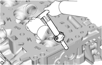
1. REPAIR INTAKE VALVE SEAT
NOTICE:
- While repairing the intake valve seat, make sure to constantly check the valve seat width and valve seating position.
- Release the cutter gradually to make the intake valve seat smooth.
| (a) Using a 45° cutter, resurface the intake valve seat so that the intake valve seat width is more than the standard. |
|
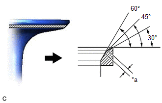
| (b) Using 30° and 60° cutters, correct the intake valve seat so that the intake valve contacts the entire circumference of the intake valve seat. The contact should be in the center of the intake valve seat, and the intake valve seat width should be as specified around the entire circumference of the intake valve seat. Standard Width: 1.0 to 1.4 mm (0.0394 to 0.0551 in.) |
|
(c) Hand lap the intake valve and intake valve seat with an abrasive compound.
(d) Check the intake valve seating position.
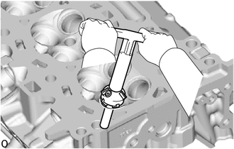
2. REPAIR EXHAUST VALVE SEAT
NOTICE:
- While repairing the exhaust valve seat, make sure to constantly check the valve seat width and valve seating position.
- Release the cutter gradually to make the exhaust valve seat smooth.
| (a) Using a 45° cutter, resurface the exhaust valve seat so that the exhaust valve seat width is more than the standard. |
|
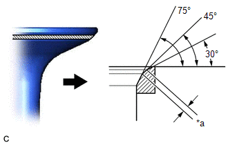
| (b) Using 30° and 75° cutters, correct the exhaust valve seat so that the exhaust valve contacts the entire circumference of the exhaust valve seat. The contact should be in the center of the exhaust valve seat, and the exhaust valve seat width should be as specified around the entire circumference of the exhaust valve seat. Standard Width: 1.2 to 1.6 mm (0.0472 to 0.0630 in.) |
|
(c) Hand lap the exhaust valve and exhaust valve seat with an abrasive compound.
(d) Check the exhaust valve seating position.


