Toyota Corolla Cross: Removal
REMOVAL
CAUTION / NOTICE / HINT
COMPONENTS (REMOVAL)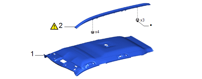
|
Procedure | Part Name Code |
.png) |
.png) |
 |
|---|---|---|---|---|---|
|
1 | ROOF HEADLINING ASSEMBLY |
63310 | - |
- | - |
|
2 | ROOF RACK ASSEMBLY |
63470B |
|
- | - |
|
● | Non-reusable part |
- | - |
CAUTION / NOTICE / HINT
HINT:
- Use the same procedure for the RH side and LH side.
- The following procedure is for the LH side.
PROCEDURE
1. REMOVE ROOF HEADLINING ASSEMBLY
Click here .gif)
2. REMOVE ROOF RACK ASSEMBLY
|
|
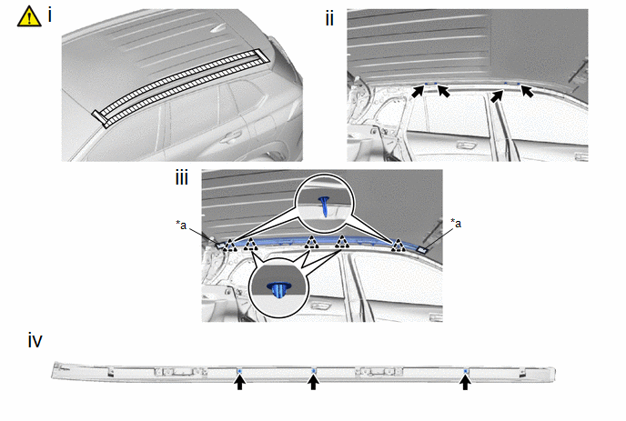
NOTICE: When removing the roof rack assembly, if the double-sided tape is difficult to remove, heat the vehicle body and roof rack assembly using a heat light. |
Standard:
|
Item | Temperature |
|---|---|
|
Vehicle Body | 40 to 60°C (104 to 140°F) |
|
Roof Rack Assembly | 20 to 30 °C (68 to 86 °F) |
CAUTION:
- Do not touch the heat light and heated parts.
- Touching the heat light may result in burns.
- Touching heated parts for a long time may result in burns.
.png)
|
*a | Heated Part |
|
*b | Heat Light |
NOTICE:
Do not heat the vehicle body and roof rack assembly.
|
*a | Double-sided Tape |
- | - |
(1) Apply protective tape around the roof rack assembly.
(2) Remove the 4 nuts.
(3) Disengage the clips and separate the double-sided tape to remove the roof rack assembly.
(4) Remove the 3 clips.


