Toyota Corolla Cross: Disassembly
DISASSEMBLY
CAUTION / NOTICE / HINT
COMPONENTS (DISASSEMBLY)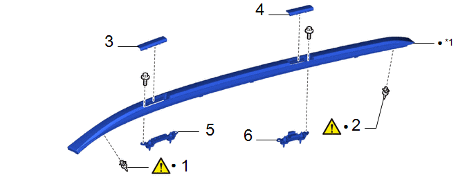
|
Procedure | Part Name Code |
.png) |
.png) |
 |
|---|---|---|---|---|---|
|
1 | FRONT ROOF RACK RETAINER |
63453F |
|
- | - |
|
2 | REAR ROOF RACK RETAINER |
63454F |
|
- | - |
|
3 | NO. 1 ROOF SIDE GARNISH LID |
75632A | - |
- | - |
|
4 | NO. 2 ROOF SIDE GARNISH LID |
75634 | - |
- | - |
|
5 | FRONT ROOF RACK LEG SUB-ASSEMBLY |
- | - |
- | - |
|
6 | REAR ROOF RACK LEG SUB-ASSEMBLY |
- | - |
- | - |
.gif)
|
*1 | ROOF RACK |
- | - |
|
● | Non-reusable part |
- | - |
CAUTION / NOTICE / HINT
HINT:
- Use the same procedure for the RH side and LH side.
- The following procedure is for the LH side.
PROCEDURE
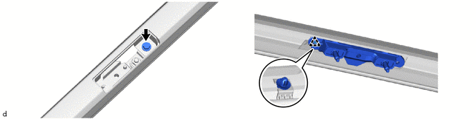
1. REMOVE FRONT ROOF RACK RETAINER

.png) |
Remove in this Direction |
- | - |
(1) Using a screwdriver with its tip wrapped in protective tape, disengage the craws to remove the front roof rack retainer as shown in the illustration.
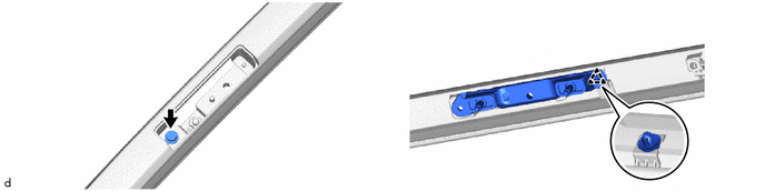
2. REMOVE REAR ROOF RACK RETAINER

|
|
Remove in this Direction |
- | - |
(1) Using a screwdriver with its tip wrapped in protective tape, disengage the craws to remove the rear roof rack retainer as shown in the illustration.
3. REMOVE NO. 1 ROOF SIDE GARNISH LID

|
|
Remove in this Direction |
- | - |
4. REMOVE NO. 2 ROOF SIDE GARNISH LID

|
|
Remove in this Direction |
- | - |
5. REMOVE FRONT ROOF RACK LEG SUB-ASSEMBLY
6. REMOVE REAR ROOF RACK LEG SUB-ASSEMBLY