Toyota Corolla Cross: Removal
REMOVAL
CAUTION / NOTICE / HINT
COMPONENTS (REMOVAL)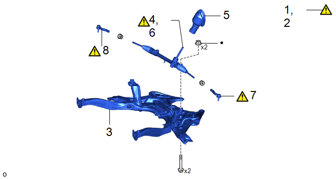
|
Procedure |
Part Name Code |
.png) |
.png) |
.png) |
|
|---|---|---|---|---|---|
|
1 |
ALIGN FRONT WHEELS FACING STRAIGHT AHEAD |
- |
|
- |
- |
|
2 |
SECURE STEERING WHEEL |
- |
|
- |
- |
|
3 |
FRONT SUSPENSION CROSSMEMBER SUB-ASSEMBLY |
51201F |
- |
- |
- |
|
4 |
REMOVE STEERING LINK ASSEMBLY |
- |
|
- |
- |
|
5 |
NO. 1 STEERING COLUMN HOLE COVER SUB-ASSEMBLY |
45025D |
- |
- |
- |
|
6 |
SECURE STEERING LINK ASSEMBLY |
- |
|
- |
- |
|
7 |
TIE ROD END SUB-ASSEMBLY LH |
45047 |
|
- |
- |
|
8 |
TIE ROD END SUB-ASSEMBLY RH |
45046 |
|
- |
- |
|
● |
Non-reusable part |
- |
- |
CAUTION / NOTICE / HINT
The necessary procedures (adjustment, calibration, initialization, or registration) that must be performed after parts are removed, installed, or replaced during the steering link assembly removal/installation are shown below.
Necessary Procedures After Procedure Performed|
Replaced Part or Performed Procedure |
Necessary Procedure |
Effect/Inoperative Function when Necessary Procedure not Performed |
Link |
|---|---|---|---|
|
Front wheel alignment adjustment |
for HEV Model:
|
|
|
for Gasoline Model:
|
|
|
|
for Gasoline Model AWD:
|
Dynamic torque control AWD system |
|
|
|
Suspension, tires, etc. |
Rear television camera assembly optical axis (Back camera position setting) |
Parking Assist Monitor System |
|
|
Initialize headlight ECU subassembly LH |
Automatic headlight beam level control system |
|
|
|
End position initial setting |
Power steering system |
|
PROCEDURE
1. ALIGN FRONT WHEELS FACING STRAIGHT AHEAD
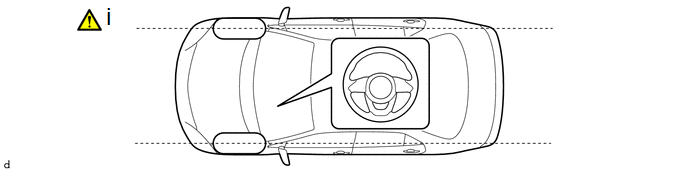
(1) Align the front wheels facing straight ahead.
2. SECURE STEERING WHEEL
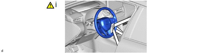
(1) Secure the steering wheel with the seat belt to prevent damage to the spiral cable by rotation of the steering wheel.
3. REMOVE FRONT SUSPENSION CROSSMEMBER SUB-ASSEMBLY
Click here .gif)
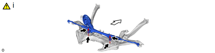
4. REMOVE STEERING LINK ASSEMBLY
 |
Front of the Vehicle |
- |
- |
(1) Remove the 2 bolts, 2 nuts and steering link assembly from the front suspension crossmember sub-assembly.
NOTICE:
Because the nut has its own stopper, do not turn the nut. Loosen the bolt with the nut secured.
5. REMOVE NO. 1 STEERING COLUMN HOLE COVER SUB-ASSEMBLY

6. SECURE STEERING LINK ASSEMBLY
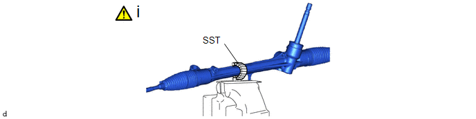
(1) Using SST with wrapped in protective tape, secure the steering link assembly in a vise.
SST: 09612-00012
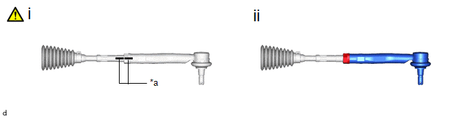
7. REMOVE TIE ROD END SUB-ASSEMBLY LH
|
*a |
Matchmark |
- |
- |
(1) Put matchmarks on the tie rod end sub-assembly LH and steering gear assembly.
(2) Remove the tie rod end sub-assembly LH and lock nut.
8. REMOVE TIE ROD END SUB-ASSEMBLY RH
(a) Perform the same procedure as for the LH side.


