Toyota Corolla Cross: Disassembly
DISASSEMBLY
CAUTION / NOTICE / HINT
COMPONENTS (DISASSEMBLY)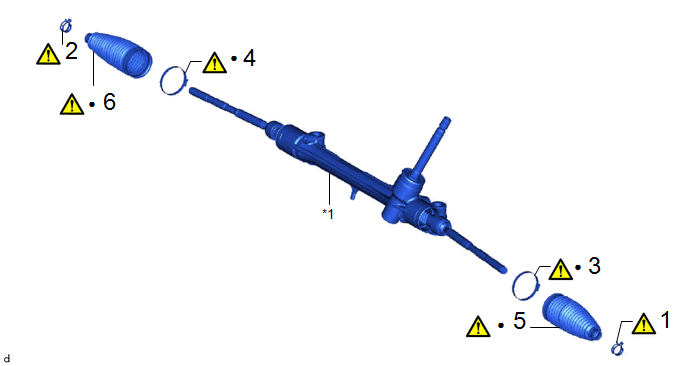
|
Procedure |
Part Name Code |
.png) |
.png) |
.png) |
|
|---|---|---|---|---|---|
|
1 |
STEERING RACK BOOT CLIP (for LH Side) |
45535B |
|
- |
- |
|
2 |
STEERING RACK BOOT CLIP (for RH Side) |
45535B |
|
- |
- |
|
3 |
STEERING RACK BOOT CLAMP (for LH Side) |
45535A |
|
- |
- |
|
4 |
STEERING RACK BOOT CLAMP (for RH Side) |
45535A |
|
- |
- |
|
5 |
NO. 1 STEERING RACK BOOT |
45535 |
|
- |
- |
|
6 |
NO. 2 STEERING RACK BOOT |
45536 |
|
- |
- |
.gif)
|
*1 |
STEERING GEAR ASSEMBLY |
- |
- |
|
● |
Non-reusable part |
- |
- |
PROCEDURE
1. REMOVE STEERING RACK BOOT CLIP (for LH Side)
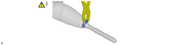
(1) Using pliers, remove the steering rack boot clip.
2. REMOVE STEERING RACK BOOT CLIP (for RH Side)
(a) Perform the same procedure as for the LH side.
3. REMOVE STEERING RACK BOOT CLAMP (for LH Side)
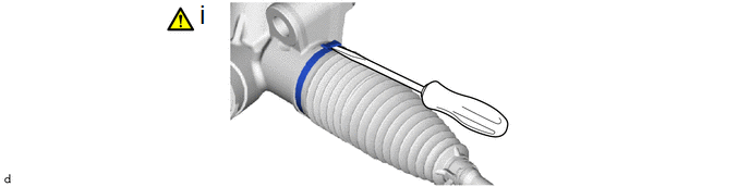
(1) Using a screwdriver, remove the steering rack boot clamp.
NOTICE:
Be careful not to damage the No. 1 steering rack boot.
4. REMOVE STEERING RACK BOOT CLAMP (for RH Side)
(a) Perform the same procedure as for the LH side.
5. REMOVE NO. 1 STEERING RACK BOOT
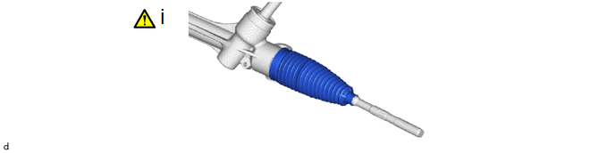
(1) Remove the No. 1 steering rack boot.
NOTICE:
- Check that there is no water, foreign matter or rust inside of the removed No. 1 steering rack boot.
- If there is no water, foreign matter or rust inside of the No. 1 steering rack boot, pull out the rack bar and check for water, foreign matter or rust.
- If water or foreign matter in either part, replace them with a new steering gear assembly.
- In order to avoid water or foreign matter from adhering to the parts, do not touch the parts unless working in a dust-free, indoors environment.
6. REMOVE NO. 2 STEERING RACK BOOT
(a) Perform the same procedure as for the LH side.


