Toyota Corolla Cross: Removal
REMOVAL
CAUTION / NOTICE / HINT
COMPONENTS (REMOVAL)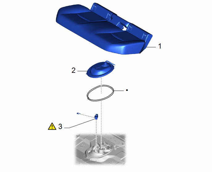
|
Procedure | Part Name Code |
.png) |
.png) |
 |
|---|---|---|---|---|---|
|
1 | REAR SEAT CUSHION ASSEMBLY |
- | - |
- | - |
|
2 | REAR FLOOR SERVICE HOLE COVER |
58325M | - |
- | - |
|
3 | FUEL TANK PRESSURE SENSOR (VAPOR PRESSURE SENSOR) |
89461 |
|
- | - |
|
● | Non-reusable part |
- | - |
PROCEDURE
1. REMOVE REAR SEAT CUSHION ASSEMBLY
Click here
.gif)
2. REMOVE REAR FLOOR SERVICE HOLE COVER
Click here
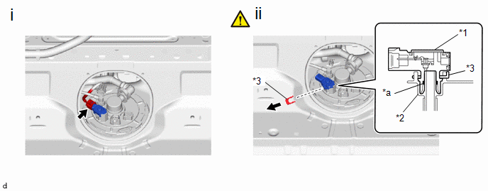
3. REMOVE FUEL TANK PRESSURE SENSOR (VAPOR PRESSURE SENSOR)
|
*1 | Fuel Tank Pressure Sensor (Vapor Pressure Sensor) |
*2 | Fuel Suction Plate Sub-assembly |
|
*3 | Tube Joint Clip |
- | - |
|
*a | O-ring |
- | - |
(1) Disconnect the fuel tank pressure sensor (vapor pressure sensor) connector.
(2) Remove the tube joint clip and pull off the fuel tank pressure sensor (vapor pressure sensor) from fuel suction plate sub-assembly.
NOTICE:
- Remove any dirt or foreign matter on the fuel tank pressure sensor (vapor pressure sensor) before performing this work.
- Do not allow any scratches or foreign matter to get on the parts when disconnecting them as the fuel tank pressure sensor (vapor pressure sensor) has an O-ring that seals the fuel suction plate sub-assembly.
- Perform this work by hand. Do not use any tools.
- If the fuel suction plate sub-assembly and fuel tank pressure sensor (vapor pressure sensor) are stuck, carefully wiggle or push and pull the fuel tank pressure sensor (vapor pressure sensor) to release it. Pull the fuel tank pressure sensor (vapor pressure sensor) off the fuel suction plate sub-assembly carefully.


