Toyota Corolla Cross: Installation
INSTALLATION
CAUTION / NOTICE / HINT
COMPONENTS (INSTALLATION)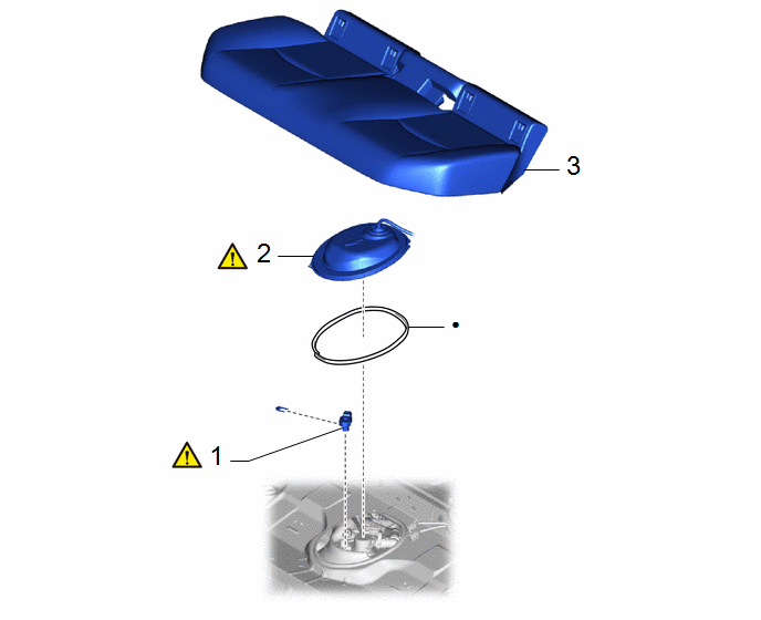
|
Procedure | Part Name Code |
.png) |
.png) |
 |
|---|---|---|---|---|---|
|
1 | FUEL TANK PRESSURE SENSOR (VAPOR PRESSURE SENSOR) |
89461 |
|
- | - |
|
2 | REAR FLOOR SERVICE HOLE COVER |
58325M |
|
- | - |
|
3 | REAR SEAT CUSHION ASSEMBLY |
- | - |
- | - |
|
● | Non-reusable part |
- | - |
PROCEDURE
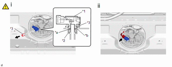
1. INSTALL FUEL TANK PRESSURE SENSOR (VAPOR PRESSURE SENSOR)
|
*1 | Fuel Tank Pressure Sensor (Vapor Pressure Sensor) |
*2 | Fuel Suction Plate Sub-assembly |
|
*3 | Tube Joint Clip |
- | - |
|
*a | O-ring |
*b | Collar |
(1) Push the fuel tank pressure sensor (vapor pressure sensor) onto the fuel suction plate sub-assembly, then install the tube joint clip.
NOTICE:
- Check that there are no scratches or foreign matter around the connecting parts of the fuel tank pressure sensor (vapor pressure sensor) and fuel suction plate sub-assembly before performing this work.
- Check that the fuel suction plate sub-assembly is securely inserted to the end of the fuel tank pressure sensor (vapor pressure sensor).
- Check that the tube joint clip is on the collar of the fuel tank pressure sensor (vapor pressure sensor).
- After installing the tube joint clip, check that the fuel tank pressure sensor (vapor pressure sensor) cannot be pulled out.
(2) Connect the fuel tank pressure sensor (vapor pressure sensor) connector.
2. INSTALL REAR FLOOR SERVICE HOLE COVER
|
|
Click here |
3. INSTALL REAR SEAT CUSHION ASSEMBLY
Click here
.gif)


